


- Product Describe
-
TL127-20C Model
Pavement Material Strength Tester
User Manual
I. Purpose and Features of the Instrument:
The main unit of the Pavement Material Strength Tester (Dual-Speed) is an improved design based on the original single-speed model. This instrument is a versatile piece of equipment designed for conducting laboratory tests on highway subgrade and pavement materials. With its accompanying accessories, it can measure the unconfined compressive strength of various soil samples, as well as their indirect tensile strength (through splitting tests) and California Bearing Ratio (CBR) tests—including measurements of swelling under water saturation. Additionally, it is capable of assessing the thermal stability and resistance to plastic flow in asphalt mixtures by determining stability and flow values (using the Marshall test), along with numerous other experiments that require the application of vertical loading.II. Main Specification Parameters of the Pavement Material Strength Tester:
1. Maximum rated load of the instrument: 200 kN
2. Maximum travel distance of the lead screw plate: 125mm
3. Motor specifications: 380V, 370W, 1400 rpm
4. Instrument maneuvering speed:A fast 50 mm/min
Slow speed, 1 mm/min
5. Instrument manual speed: 1/6 mm/rev
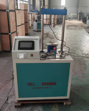
III. Key Structure of the Pavement Material Strength Tester:
This instrument features a two-column structure: it consists of an outer casing, gearbox, upright columns, flat platform, television, and electrical switches, among other components.The electric motor (380V, 370W, 1400 rpm) transmits power to the gearbox via a belt. The gearbox, equipped with a complete set of speed-changing and selection mechanisms, enables the lead screw plate to achieve two different motor-driven lifting speeds, meeting the requirements of both the Marshall test and the Load-Carrying Ratio test. To ensure the maximum lifting distance of the lead screw plate meets experimental needs, the instrument is fitted with a manual control mechanism for adjusting the plate's vertical movement. Additionally, a fixed screw is mounted on the support structure, allowing the appropriate load-ring assembly to be securely fastened to the support for testing purposes.
The electrical switch can control the motor's forward rotation, reverse rotation, and stop.
IV. Operation and Usage
The instrument should be operated as follows:
Ahead of the gearbox is a mechanism selector lever: the lever has three positions—Quick, Manual, and Slow. When the selector lever is set to the Quick position and the motor is turned on, the lead screw plate achieves an ascending or descending speed of 50 mm/min, making it ideal for conducting the Marshall test on asphalt concrete. If the selector lever is placed in the Slow position and the motor is activated, the lead screw plate moves at a slower rate of 1 mm/min, perfect for tests like the California Bearing Ratio, where precision at this specific speed is crucial. Finally, when the selector lever is switched to the Manual position, manual lifting and feeding operations become possible. To do this, first set the selector lever to its middle position, then use the square-head handle located on the side of the housing—by turning the handle with a crank—you can achieve a feed rate of 1/6 mm per revolution, which is suitable for other experiments requiring the application of vertical loads.When starting the test, first secure the appropriate load cell to the support frame using tightening bolts, and then attach the suitable accessory (indenter) to the load cell. Place the specimen onto the screw-driven plate, and proceed with the test. The magnitude of the load applied during the test can be read directly from the dial gauge attached to the load cell.
Note: The lifting distance of the lead screw plate should be kept within 125 mm.
V. Maintenance and Servicing of the Pavement Material Strength Tester
1. The instrument's surface should be wiped regularly to keep it clean and tidy.- The threaded section of the leadscrew plate should be lubricated with an appropriate amount of machine oil once per shift to maintain smooth operation at the joint.
 In the upper-right corner, the specimen type is entered using the diameter of the cylindrical specimen. In the lower-right corner, you’ll find the test records; simply click on a test record to view the original test documentation. The display shows the test time, test number, and test item. Clicking on the test number will reveal detailed test records. If you no longer need a particular test record, long-press the test item in that row to delete the corresponding test entry.
 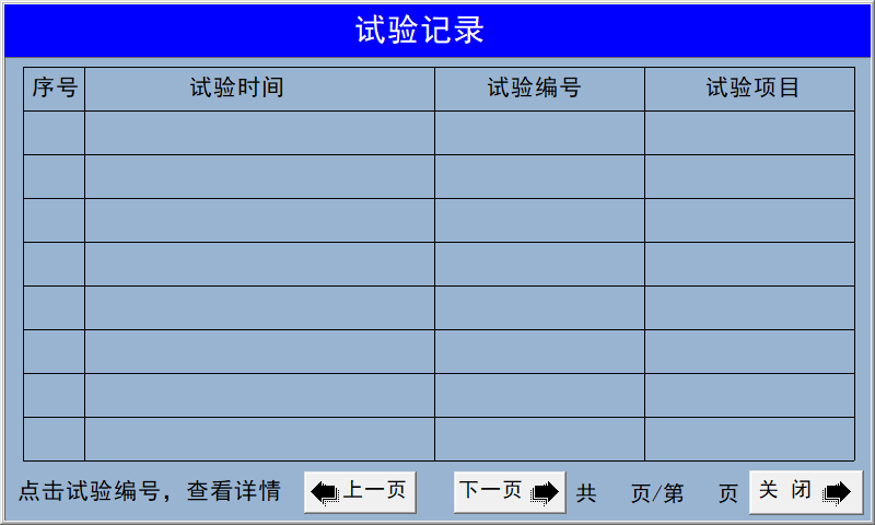 Parameter Settings Display
 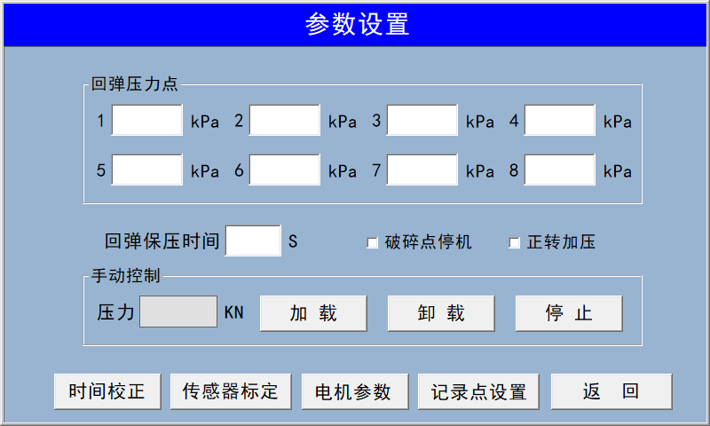 This interface allows you to modify time settings, calibrate sensors, adjust motor parameters, set CBR recording points, and input rebound test pressure values.
 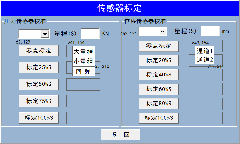 To calibrate the pressure sensor, click the downward arrow in the top-left corner—it will bring up three dialog boxes: Large Range (100 kN), Small Range (50 kN), and Rebound (5 kN). Select the appropriate range for the sensor you wish to calibrate, then manually apply pressure.
For calibrating the displacement sensor, click the downward arrow—it will open a menu where you can choose Channel 1 or Channel 2 to proceed with calibration.
To calibrate the pressure sensor, click the downward arrow in the top-left corner—it will bring up three dialog boxes: Large Range (100 kN), Small Range (50 kN), and Rebound (5 kN). Select the appropriate range for the sensor you wish to calibrate, then manually apply pressure.
For calibrating the displacement sensor, click the downward arrow—it will open a menu where you can choose Channel 1 or Channel 2 to proceed with calibration. 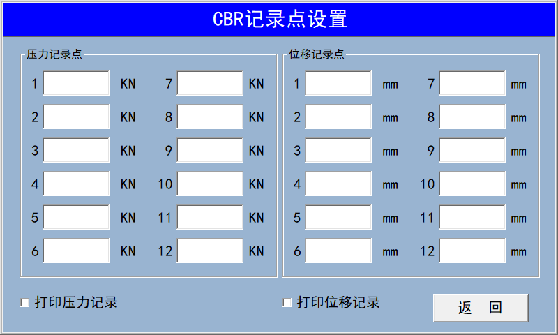 Please enter the recording point manually, or use the default recording point.
 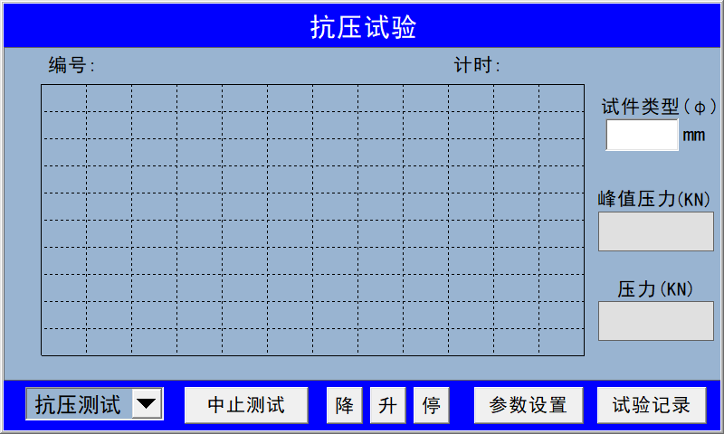 On this interface, select the type of test you need to perform, then click the downward arrow in the lower-left corner to open the options: compression test, CBR test, and rebound test. After choosing your desired test type, install the pressure sensor and get ready to start the experiment.
- The threaded section of the leadscrew plate should be lubricated with an appropriate amount of machine oil once per shift to maintain smooth operation at the joint.
Company Profile
Hebei Yinfeng Experimental Instrument Co., Ltd. is a high-tech enterprise dedicated to the research and development, production, and sales of experimental instruments. The company is headquartered in Hebei Province, relying on the strong industrial foundation and technological innovation resources in the Beijing Tianjin Hebei region. It is committed to providing high-precision and high reliability testing equipment and solutions for material testing, engineering quality control, scientific research experiments and other fields.


Customized Delivery Process
We provide customers with full-process services ranging from pre-sale consultation, customized solution design, equipment installation and commissioning to after-sale technical support.
Online Communication
Provide Custom Drawings
Merchant Quotation
Sign A Contract
Processing And Production
Packaging And Distribution
Confirm Receipt Of Goods
Successful Transaction
TL127-20C Type Pavement Material Strength Tester
If you need customized products, Contact US !
Share to


Category
Tag list
Request a Quote
We will contact you within one working day. Please pay attention to your email.
Related Products
Content update in progress
Message
We will contact you within one business day. Please note your email address.
Fast navigation
Contact Us
Whatsapp/Tel: +86-15931715356,+86 16631790555
E-mail: info@cnhblabequipment.com
Add: Chengnan Industrial Zone, Xian County, Cangzhou City, Hebei Province