

- Product Describe
-
Equipment Name: Static Cone Penetrometer
Device Model: CLD-3A
Overview:
The CLD-3A static cone penetrometer uses mechanical transmission to steadily press the probe into the soil.
Suitable for testing in strata such as soft soil, cohesive soil, loess, and sandy soil, this device utilizes the resistance generated when the probe comes into contact with the soil layer. The resulting changes in electrical resistance are transmitted to measuring instruments on the ground. The entire unit features lightweight components, compact dimensions, easy portability, convenient installation, and high operational efficiency. It can also be equipped with probes and sensors of various diameters.
- Technical Specifications
- Structural forms: Main unit (complete machine), ground anchor, hand-crank type.
- Rated penetration force: CLD-3 30 kN.
- Cross-plate shear: <132 kPa
- Tensile strength: 15 kN, 25 kN.
- Penetration speed: 1.2 meters per minute.
- Host weight: 60 kg.
- How it works
- Connect the main unit to the beam (9) using screws.
- Select the anchor points based on the length of the beam, and drive two ground anchors (11) into the soil—on both sides of the main unit.
- You can drop the anchor using the anchor lowering lever with the force tube (7), with two people pushing steadily, or by using large pipe wrenches to lower the anchor.
- Install the host between the two anchor rods, ensuring it is placed horizontally and securely filled with soil—make sure it cannot be shaken.
- Attach the ground anchor clamp (12) onto the ground anchor rod and place it on the crossbeam.
- Arrange the probe rods one by one, threading the cables through them individually. Connect one end to the probe—secure the cable connections tightly with waterproof tape—to ensure no water seeps inside the cables (as water intrusion could damage the probe). Then, connect the other end to the instrument.
- Attach the probe to the probe rod, then carefully thread it through both the upper and lower holes. Secure each probe rod one by one by tightening the connectors at the joints. Next, place the guide sleeves (2) and (10) onto the lower holes of the main unit, clamping the probe rods firmly in place to prevent any lateral movement.
- Insert the locking block (5) into the probe joint, and as you press it into the soil, place a wedge-shaped pressure plate (6) on top of the locking block. Then, gently shake the main unit handle to rotate the chains on both sides of the host machine. The chain stop pins (4) on either side of the chains will securely hold the wedge-shaped plate in place, allowing you to steadily push the probe tip into the ground at a uniform speed.
- When extracting, place the mountain-shaped plate beneath the locking block, then reverse-rotate the main handle to slowly lift the probe rod upward at a steady pace.
- The cross-plate test (available separately upon customer request) involves placing the worm gear box onto the main unit using the same method. Note that each full rotation of the worm gear box handle corresponds to 1 degree—simply record this data.
- When conducting an undisturbed soil shear test using a vane, insert the vane to the test depth, allow it to stand still for 2–3 minutes, and then begin the undisturbed soil vane shear test.
- After completing the undisturbed soil shear test, rotate the vane six full turns along the shear direction to thoroughly disturb the surrounding soil, and then proceed with the remolded soil shear test.
- Important Notes
- When using the machine for the first time after it leaves the factory, users should apply oil or grease between all gears and sprockets, and during the break-in period, always consult a mechanical professional for adjustments.
- If a cross-plate shear test is required, you’ll need to purchase a worm gear box to place on top of the main unit; all other procedures remain the same.
- Please oil, clean, and store each item after finishing work to prevent rusting.
- The probe rod from our factory undergoes heat treatment, ensuring that both its hardness and toughness exceed those of ordinary steel—and the joints also require lubrication.
- The probe must be disassembled, washed, and lubricated after use.
IV. After-Sales Matters
1. If quality issues are discovered one month after the purchase of this instrument, and as long as the exterior shows no damage and the user has not attempted any self-repair or disassembly, a full unit replacement (excluding the exterior) can be requested with the original invoice.
2. For all instruments sold, the warranty period is one year, calculated from the invoice date. If the user independently disassembles or repairs the equipment without authorization from the manufacturer or dealer, or if improper use or damage results in irreparable issues, the user shall bear full responsibility.
3. After the warranty period, the manufacturer will still handle repairs, charging only for labor and materials.
V. The probe must be properly stored and protected against water ingress. Secure the cable connectors tightly with waterproof tape to prevent moisture from entering. Please note that the probe is a consumable item and is not covered under warranty. It should be periodically calibrated based on usage conditions. If the probe has been used beyond its recommended one-year lifespan, we strongly recommend replacing it with a new unit. Additionally, please return both the original probe and instrument to our factory for professional inspection and recalibration—this ensures that electronic components do not deteriorate and maintains the probe’s sensitivity, thereby guaranteeing the accuracy of your measurement data. (However, if on-site testing continues to show excellent performance, you may choose not to replace the probe; instead, you can manually adjust the meter for calibration.)
6. If you encounter any other unresolved technical issues, please contact your dealer promptly. Thank you for choosing our product—we’ll do our best to serve you.
Host Diagram
CLD-3A Static Cone Penetrometer Configuration List
Serial Number Name Unit Quantity Note 1 Host rack Taiwan 1 2 Probe rod Root 20 3 Ground anchor Root 2 4 Ground anchor pressure iron Only 2 5 Ground Anchor Rod Holder Only 2 6 Lower the anchor and add the lever rod Root 2 7 Crank handle Only 2 8 Mountain-shaped clamp Only 1 9 Card Block Only 1 10 Guide sleeve Pay 2 11 Probe connector One 1 12 Measuring instruments Taiwan 1 Or quietly explore the microcomputer 13 Single-bridge probe Only 1 14 Reducing coupling Only 20 15 4-core cable Rice 25 Instruction Manual for the Static Cone Penetrometer Controller
I. Overview
This system features a high-performance, low-power microprocessor and is equipped with a 3.5-inch color touchscreen offering HD display. The data acquisition module utilizes a high-precision AD conversion chip, ensuring accurate and stable data collection. For storage, a large-capacity memory device is employed, capable of recording data from up to 300 measurement points. The system is powered by a robust lithium battery rated at up to 5000mA, allowing for continuous operation lasting over 30 hours.
II. Page Introduction
1. Power-on Screen
2. After clicking "Enter Main Interface," the following will be displayed:
“Settings” button: Used for parameter settings and calibration data.
“Query” key: Query test data.
“Retry” button: If the experiment is unexpectedly interrupted, you can press this button after restoring power to resume the previous trial.
"Test" button: Start the test.
III. Important Notes:
Please do not operate the system calibration data if you are not from the metrology department.
Company Profile
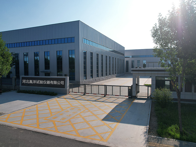
Hebei Yinfeng Experimental Instrument Co., Ltd. is a high-tech enterprise dedicated to the research and development, production, and sales of experimental instruments. The company is headquartered in Hebei Province, relying on the strong industrial foundation and technological innovation resources in the Beijing Tianjin Hebei region. It is committed to providing high-precision and high reliability testing equipment and solutions for material testing, engineering quality control, scientific research experiments and other fields.


Customized Delivery Process
We provide customers with full-process services ranging from pre-sale consultation, customized solution design, equipment installation and commissioning to after-sale technical support.
Online Communication
Provide Custom Drawings
Merchant Quotation
Sign A Contract
Processing And Production
Packaging And Distribution
Confirm Receipt Of Goods
Successful Transaction
Previous:


Single-bridge static cone penetrometer. Static cone penetrometer
If you need customized products, Contact US !
Category
Tag list
Request a Quote
We will contact you within one working day. Please pay attention to your email.
Related Products
Content update in progress


