


- Product Describe
-
Main Uses and Applicable Scope of the Testing Machine
Applicable for testing the bonding strength of insulation materials, dry-mixed mortar, ceramic wall and floor tile adhesives, multi-layer architectural coatings, and putty for building exterior walls. Complies with JC/T547-2005, GB/T9779-2005, JG/T157-2004, JC/T890-2017 standards for testing bonding strength of various building materials. Suitable for production inspection and research in factories, construction project quality inspection stations, construction companies, product quality inspection institutes, and research institutions.
1. Main specifications, technical parameters, and indicators of the testing machine:
(1) Maximum test force: 10000N.
(2) Effective measurement range of test force: 10N-10000N.
(3) Minimum resolution of test force: 0.1N.
(4) Pulling method: adjustable constant speed and constant force.
(5) Pulling speed range: 1mm~300mm/min.
(6) Test head tensile range: 100mm.
(7) Specimen size: 400mm x 400mm or 400mm x 200mm.
(8) Maximum specimen thickness: 60mm.
(9) Clamp type: joint-type T-shaped clamp.
(10) Power supply: 220V.
2. Working conditions of the testing machine
(1) Ambient temperature between 10-30 degrees Celsius.
(2) Relative humidity less than or equal to 80%.
(3) In a vibration-free environment.
(4) Correctly installed on a stable foundation or workbench.
(5) No corrosive media in the surrounding environment.
(6) Power supply voltage fluctuation should not exceed ±10% of the rated voltage.
3. Structural features and working principle of the testing machine: This machine consists of mechanical and electrical parts.
Panel and buttons
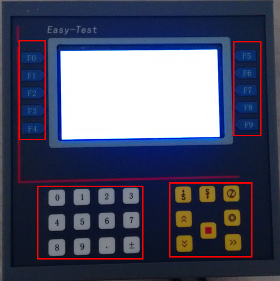
2. Movement and control keys
1. Data input keys
Data input keys
Used for numerical input.
Movement and control keys
 Acceleration key.
  Deceleration key.
  Zeroing key, clears all values (force, displacement, deformation).
  Up key.
  Down key.
  Test key.
  Reset key, moves the crossbeam to zero position.
  Stop key.
 F0~F9 function keys
The functions executed by the function keys are indicated by the screen menu bar next to them.
Display and operation
(1) Main interface
1. Data display area
Menu bar
Menu bar
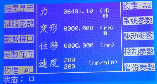
2. Status display
After system startup, the main interface is displayed first. The main interface is shown in the above figure.
Data display area:
Displays real-time data including force, displacement, deformation, etc. It also shows the current running speed and return speed of the system, where the upper speed value is the running speed and the lower speed value is the return speed.
Status display:
Displays the current running status, limit status, online status, parameter saving status, etc. as shown below:

Save status
Upper and lower limit status
Running status
Menu bar
Pressing each button F0~F9 next to the menu will execute the function of that menu. The following will introduce them one by one.
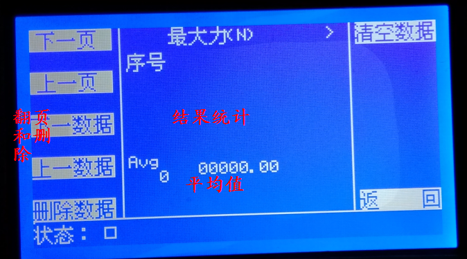
(2) Result display
Press "Result Display" in the main menu to enter the "Result Display" interface.

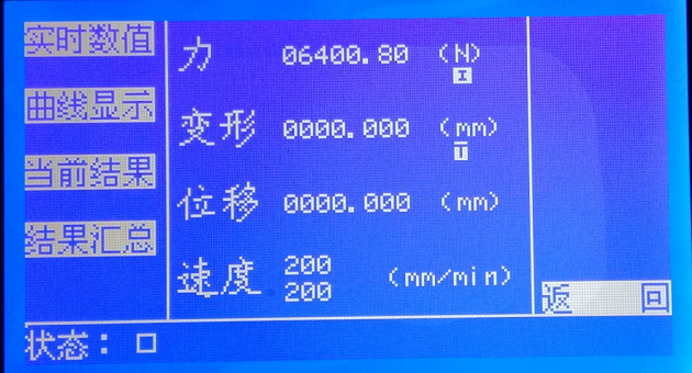
In this interface, you can select menus to display real-time data, display curves, display current results, and result summaries, as shown below.
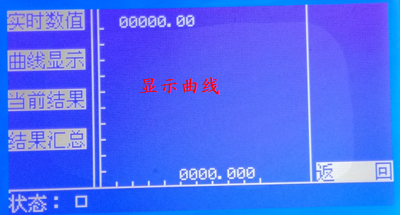
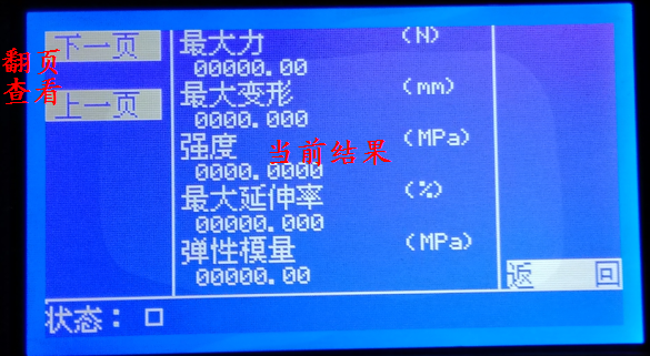
On each page, you can return to the previous interface or main interface through the "Return" menu.
(3) Test parameters
Press "Test Parameters" in the main menu to enter the "Test Parameters" interface. Enter data related to the test in this interface.

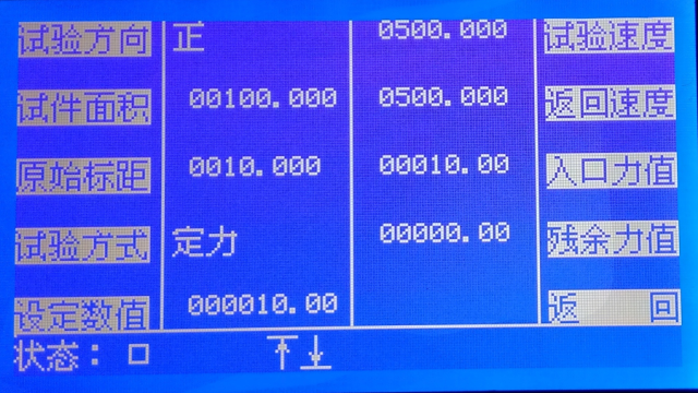
1. Test direction
Set the test direction to switch between "forward" and "reverse."
2. Specimen area
Set the original cross-sectional area of the material (mm²);
3. Original gauge length
Set the original gauge length of the material (mm);
4. Test method
Select the test method, including fracture test, fixed displacement test, fixed deformation test, fixed force test, constant force fracture, etc.;
5. Set value
Set values related to the test method. For example: if test method = fracture test and set value = 15.0, it means the test ends when the force decreases by 15.0N (or kN); if test method = fixed displacement and set value = 15.0, it means the test ends when displacement reaches 15.0mm;
6. Test speed
Set the test speed, which is also the usual speed of the crossbeam moving up and down (this speed is the maximum speed, and the actual speed can be adjusted using the acceleration key
 and the deceleration key
  to adjust).
 7. Return speed
This is the speed at which the crossbeam automatically resets after the test ends. If this value is 0, the crossbeam will not automatically reset after the test.
8. Entry force value
During the test, deformation of the specimen is only calculated when the force reaches this value.
9. Residual force value
This is the break force. After the specimen breaks, there may still be some residual force. During the test, when the measured force is less than this value, the specimen is considered broken.
After setting the test parameters, press the test button on the main interface
 to start the test. When the test starts, displacement and deformation are reset to zero, then the machine runs according to the set test speed and direction. Before the test force reaches the set entry force, deformation is always counted as zero, while displacement records the crossbeam movement in real time. Once the test force reaches the entry force, the specimen's deformation is recorded. The system judges whether the test ends based on the user-set test method and corresponding parameters. After the test ends, the system controls the crossbeam to return at the set return speed; if the return speed is 0, it will not automatically return. During the test, operations such as "Parameter Setting" and "Calibration" cannot be used.
 (4) Data Interface
Press the "Data Interface" menu in the main menu to enter the "Data Interface" screen. Here you can set the data sources for each data and perform zeroing operations on each interface's data.

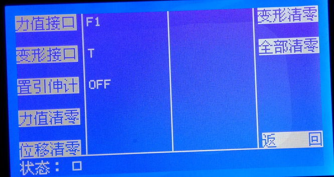
Force Interface
The system has two analog sensor interfaces; the force interface can be switched between F1 or F2.
Deformation Interface
Deformation data can come from three sources:
L, obtained from displacement
S, obtained from extensometer small deformation
T, obtained from large deformation.
You can switch through this menu.
Set Extensometer
Used to turn the extensometer on or off, setting whether the controller connects the extensometer on analog channel 2. ON means connected, OFF means not connected. Connecting the extensometer on analog channel 2 occupies the second force sensor channel, so the controller can only connect to one force sensor.
Zeroing Values
Allows zeroing of specified values.
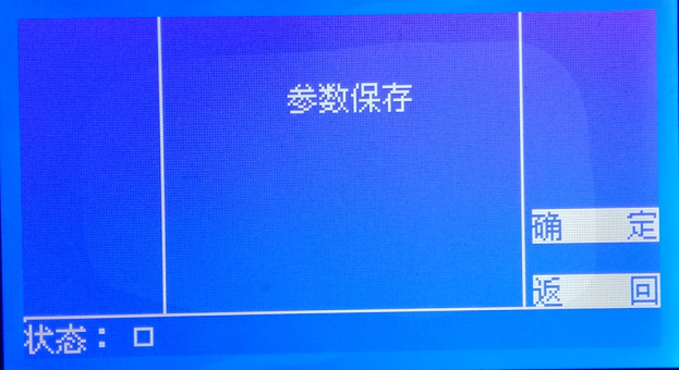
(5) Parameter Saving
Press the "Parameter Saving" menu in the main menu to enter the "Parameter Saving" screen. Here, parameters can be saved by pressing the "Confirm" menu. After modifying controller parameters, you must save the settings; otherwise, the controller will use the previous parameters on next startup. Especially after calibration, saving is mandatory.

(6) Calibration A1
The system can connect two analog sensors. Before calibration, you must switch the force sensor to be calibrated to the current channel on the "Data Interface" page, then proceed with calibration. To calibrate A1, set the force interface to F1; to calibrate A2, set the force interface to F2.
Below is an example of calibration for sensor one.
Step 1: Completely unload the sensor.
Step 2: Press "Calibrate A1" on the main interface to enter the calibration screen.
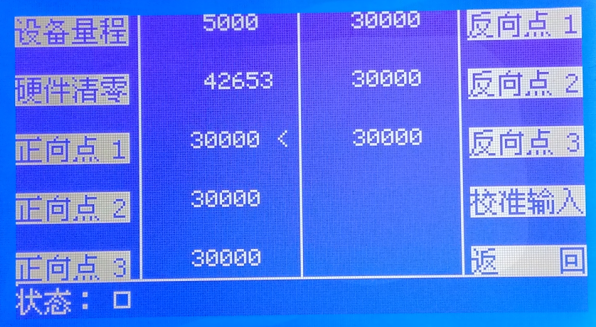
Step 3: In the calibration screen, input the correct sensor range via the "Device Range" menu, and set the sensor zero point correctly using "Hardware Zeroing." After setting correctly, the zero value should be 0 (or slightly fluctuating).
In the calibration screen, Forward 1~3 are the three positive calibration coefficients of the sensor, and Reverse 1~3 are the three negative calibration coefficients. Users adjust and calibrate the sensor by setting these values. During actual calibration, users can quickly calibrate via "Calibration Input" without manually modifying these values.
Step 4: Load the sensor to the calibration value, then input the correct load value via "Calibration Input." Press "Confirm" to perform a single-point calibration.
In Calibration Input, you can also select "Single Point Application," where each calibration only calibrates one of the six data points. Six single-point applications are required to complete full-range calibration, achieving multi-point calibration.
After calibration, you must save the calibration parameters.
(7) Calibration A2
The method is the same as Calibration A1.
(8) System Parameters
Press the "System Parameters" menu in the main menu to enter the "System Parameters" screen.

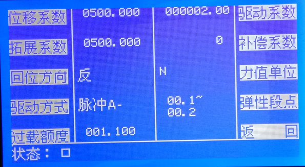
Displacement Coefficient: Parameter for calibrating displacement. It means the number of pulses corresponding to 1mm of device movement. If you know this pulse count, input it directly; if not, determine it by measurement: first set the displacement coefficient to 1, then drive the device to move 1mm, read the displacement on the screen, and input this displacement as the displacement coefficient.
Extension Coefficient: Used for calibrating large deformation. It means the number of pulses generated by the large deformation sensor moving 1mm. If known, input directly; if unknown, determine by measurement: first set the extension coefficient to 1, switch the deformation channel to T to activate the large deformation sensor, zero the deformation, then drive the large deformation to move 1mm, read the deformation on the screen, and input this as the extension coefficient.
Return Direction: The direction the device moves when pressing the reset key "
 ". If the return direction is incorrect, it can be switched via "Return Direction."
 Drive mode: refers to the type of output drive motor. Voltage output is used to control the variable frequency motor; pulse A0 output is used to control the servo motor or stepper motor with an external encoder; pulse A+ output is used to control the servo motor or stepper motor with the encoder taking the internal positive direction; pulse A- output is used to control the servo motor or stepper motor with the encoder taking the internal negative direction.
Overload limit: sets the overload limit of the sensor. When the sensor load value exceeds the set limit, output stops. For example, if the sensor's full scale is 1000N and the overload limit is 1.1, output will stop when the load value exceeds 1100N.
Drive coefficient: speed coefficient, adjust this value to calibrate the running speed;
Compensation coefficient: speed compensation value, adjust this value to fine-tune and correct the running speed;Force unit: the force unit can be switched between kN and N. After switching units, parameters must be saved and the system restarted to take effect.
Elastic segment point: sets the theoretical elastic range of the specimen, within which the force value and deformation amount have a linear relationship.
(9) Other reserved parameters
Reserved for backup, users cannot set.
Company Profile
Hebei Yinfeng Experimental Instrument Co., Ltd. is a high-tech enterprise dedicated to the research and development, production, and sales of experimental instruments. The company is headquartered in Hebei Province, relying on the strong industrial foundation and technological innovation resources in the Beijing Tianjin Hebei region. It is committed to providing high-precision and high reliability testing equipment and solutions for material testing, engineering quality control, scientific research experiments and other fields.


Customized Delivery Process
We provide customers with full-process services ranging from pre-sale consultation, customized solution design, equipment installation and commissioning to after-sale technical support.
Online Communication
Provide Custom Drawings
Merchant Quotation
Sign A Contract
Processing And Production
Packaging And Distribution
Confirm Receipt Of Goods
Successful Transaction
Mortar Bond Strength Pull-off Tester
If you need customized products, Contact US !
Share to


Category
Tag list
Request a Quote
We will contact you within one working day. Please pay attention to your email.
Related Products
Content update in progress
Message
We will contact you within one business day. Please note your email address.
Fast navigation
Contact Us
Whatsapp/Tel: +86-15931715356,+86 16631790555
E-mail: info@cnhblabequipment.com
Add: Chengnan Industrial Zone, Xian County, Cangzhou City, Hebei Province