


- Product Describe
-
Overview
The digital display ceramic tile flexural testing machine (hereinafter referred to as the flexural machine) uses a three-point bending beam test to reflect the mechanical properties of the material by measuring the flexural strength. It is mainly used to measure the flexural strength of ceramic tiles, tiles, and other materials. It is especially suitable for testing the bending strength of large-sized, high-strength ceramic tiles, and can also be used to determine the bending strength of brittle non-metallic material plates such as marble slabs and glass plates. This machine complies with the requirements for testing equipment in GB/T 3810.4—2006 "Test Methods for Ceramic Tiles—Part 4: Determination of Modulus of Rupture and Breaking Strength" and ISO 10545-4:1994 "Ceramic Tiles—Part 4: Determination of Modulus of Rupture and Breaking Strength." The machine features easy operation, stable loading, high measurement accuracy, and intuitive reading, making it an advanced method for studying the strength of related materials.
Main Technical Parameters
1. Maximum test force: 10000N
2. Worktable stroke: ≤70mm
3. Support roller and pressing roller radius R=15mm (externally covered with 5mm thick rubber)
4. Distance between two support rollers: 70–810mm
5. Power supply: 50Hz AC 220V±10%
6. Dimensions: 1150×850×1600(mm)
Structure Description
The flexural testing machine consists of the main unit and the digital display force measurement parts.
The main unit includes the loading system (driven by a motor with synchronous belt and pulley), base, worktable, support rollers, pressing roller, column, and sensor. The digital display force measurement part consists of a high-precision tension-compression sensor and a digital display controller. This part uses an electronic force measurement system with digital display of test results and features calibration, peak hold, and zeroing functions.
Working Principle
When ceramic tiles, tiles, and other brittle materials undergo a three-point bending test, if the test force is greater than or equal to the specimen's limit value, it will suddenly fracture. The maximum load F at the moment of fracture is used.
Installation, Debugging, and Calibration
1. Installation and leveling
(1) Leveling
After unpacking the testing machine, first check whether all pipe joints and connecting screws are loose. Then place the testing machine on a sturdy platform. Place a level on the worktable surface, support the four corners, and adjust to level.
(2) Reliable grounding of the testing machine
Use a copper wire with a cross-sectional area of no less than 1.5mm² to reliably ground the testing machine.
(3) Power on
Use a 50Hz, 220V AC power supply and check whether the sensor connection wires are properly connected.
Interface and Functions
1.1 Welcome Interface (1-1)
Tap anywhere on the screen to enter the main test menu.

1-1
1.2 Main Menu Interface (1-2)
[Test] Tap "Test" to enter the test interface. After entering, confirm whether the test method is correct.
[Test Selection] Enter the test method selection interface to choose test methods such as tensile test, bending test (general bending test, plastic bending test, ceramic tile flexural test, and artificial board bending test), compression test, peel test, puncture test, paper tensile test, etc.
[Test Report] Tap the "Test Report" button to enter the test results interface to view and print historical data and curves.
[Calibration] Tap "Calibration" and enter the password "******" to enter the calibration selection interface. (Displacement, force values, etc., have been calibrated before the equipment leaves the factory; non-maintenance personnel are prohibited from entering).
[ Configuration] "Configuration" is important system data and requires a password to enter. Details on whether data can be modified or prohibited from modification will be explained later.
[Help] "Help" is used by equipment maintenance personnel for repair or inspection.
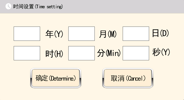
1.3 Time Setting In the main menu interface, long press the time "2023-03-08 17:38:20" for 3 seconds. A dialog as shown in figure 1-3 will pop up. Enter the accurate date and time in the boxes after year, month, day, hour, minute, and second. After input, click "Confirm".
[Language] In the lower left corner of the main menu interface,
 tap to switch between Chinese and English.
1-2
1-3
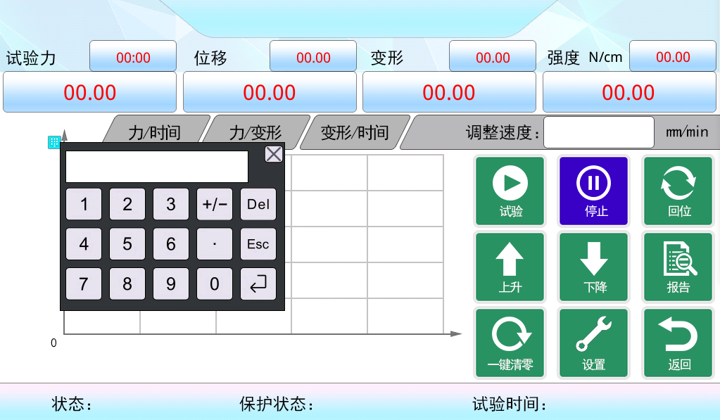
1.4 Test Interface (1-4)
[Test Force] Displays real-time force value.
[Displacement] Displays real-time displacement.
[Deformation] Displays real-time specimen deformation.
[Strength] Displays real-time specimen strength value.
[Force/Time] Y-axis represents force value, X-axis represents real-time.
[Force/Deformation] Y-axis represents force value, X-axis represents real-time deformation.
[Deformation/Time] Y-axis represents deformation, X-axis represents real-time.
[Y-Axis Coordinate Settings] Click on the Y-axis of the coordinate axis.
 A numeric keypad will pop up. Enter the sensor's maximum range value or a value that can fully display the curve. All three types of curve charts require Y-axis settings. The system saves automatically, so no need to set again after reboot. The X-axis is auto-scaled and does not require setting.
 [Adjust Speed] "Adjust Speed" refers to adjusting the motor's ascending or descending speed, not the "test speed." The "test speed" needs to be modified in the settings.
[Test] Click to start the test, record values, and plot the curve. If the curve does not appear, check (1) if the Y-axis is set too high, (2) whether the test force value is positive, and whether the displacement value is positive. If not positive, return to the main menu, click the configuration button, enter the password "******", then check the option to invert force or displacement values, save, and return.
[Stop] Stop the test operation.
[Return to Position] After clicking test, if the test ends without returning to the origin, click "Return to Position" to move the crossbeam back to the position before the test started.
[Ascend] Crossbeam ascends.
[Descend] Crossbeam descends.
[Report] View test results and historical curves.
[One-Click Zeroing] Clear test force, displacement, deformation, and strength values.
[Settings] Enter the settings interface to configure test parameters.
[Return] Return to the main menu interface.
[Status] Displays motor status: stopped, ascending, descending, or testing.
[Protection Status] Displays protection status: idle (normal testing possible), upper limit protection, lower limit protection, force protection, force speed protection, speed protection, etc. If any protection occurs during testing, the test ends. If protection appears before the test is completed, no test results will be generated. Check the cause of protection, resolve it, and retest.
[Test Time] The timer starts after the preload force, marking the official start of the test.
[Test Method] The current test type, such as tensile test, bending test, etc.
1-4
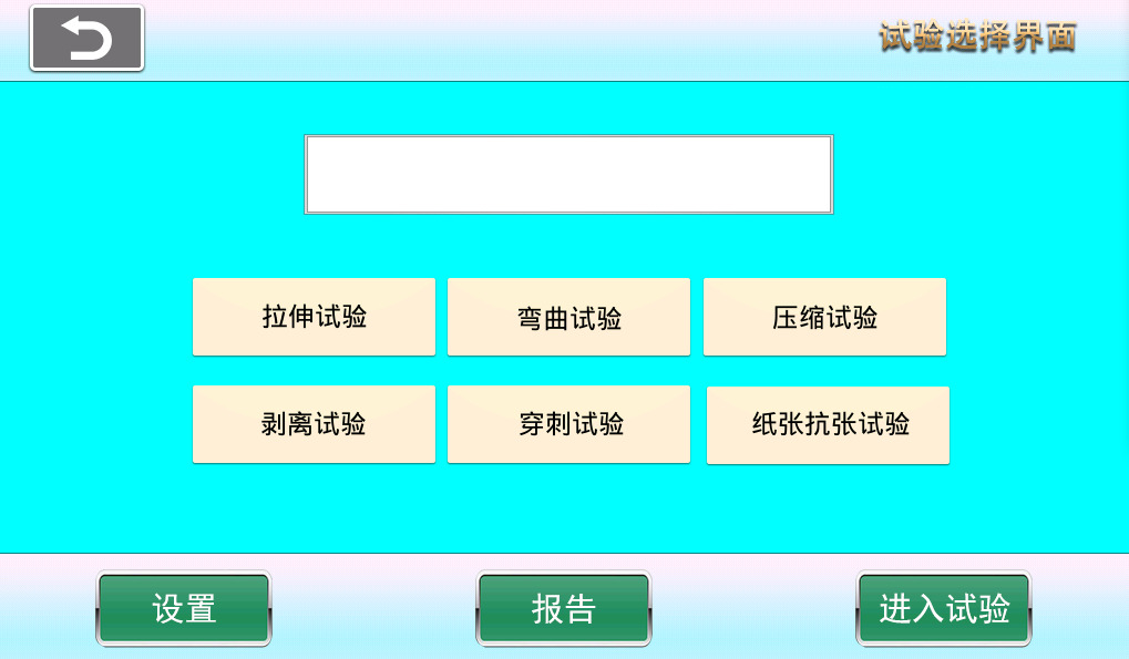
1.5 Test selection (1-5)
[Tensile Test] After clicking "Tensile Test," the rectangle above will display "Tensile Test." Then clicking settings, report, or entering the test will all operate under the "Tensile Test" mode, including main menu configuration parameters based on tensile test operations.
[Bending Test] After clicking "Bending Test," the rectangle above will display "Bending Test." Then clicking settings, report, or entering the test will all operate under the "Bending Test" mode, including main menu configuration parameters based on bending test operations.
[Compression Test] After clicking "Compression Test," the rectangle above will display "Compression Test." Then clicking settings, report, or entering the test will all operate under the "Compression Test" mode, including main menu configuration parameters based on compression test operations.[Peeling Test] After clicking "Peeling Test," the rectangle above will display "Peeling Test." Then clicking settings, report, or entering the test will all operate under the "Peeling Test" mode, including main menu configuration parameters based on peeling test operations.
[Puncture Test] After clicking "Puncture Test," the rectangle above will display "Puncture Test." Then clicking settings, report, or entering the test will all operate under the "Puncture Test" mode, including main menu configuration parameters based on puncture test operations.
[Paper Tensile Test] After clicking "Paper Tensile Test," the rectangle above will display "Paper Tensile Test." Then clicking settings, report, or entering the test will all operate under the "Paper Tensile Test" mode, including main menu configuration parameters based on paper tensile test operations.
[Settings] After selecting the test method, click settings to enter the corresponding test settings.
[Report] After selecting the test method, click report to enter the corresponding test report.
[Enter Test] After selecting the test method, click "Enter Test" to enter the corresponding test interface.
1-5
1.6 Tensile Test
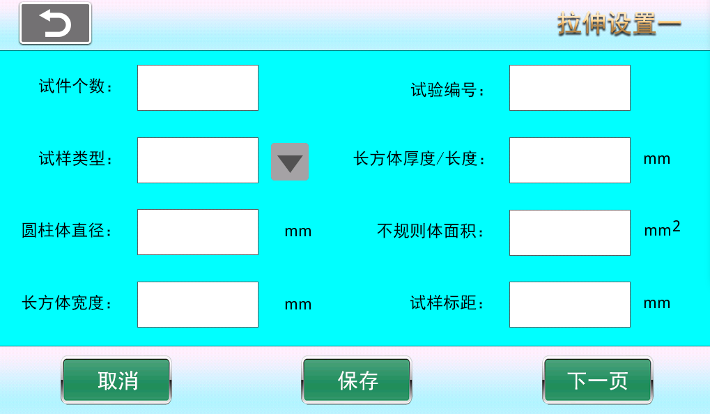
(1) Tensile Test Setting One (L-1)
L-1
[Number of Specimens] Select the number of specimens from 1 to 10. The test result interface will display the number of specimens per page after testing.
[Test Number] The number of each page in each group or test result.
[Sample Type] You can choose cylinder, rectangular prism, or irregular body.
[Rectangular Prism Thickness/Length] Specimen length, or thickness for some specimens.
[Cylinder Diameter] Diameter of the cylinder.
[Irregular Body Area] For irregular bodies where length or width cannot be measured, the specimen strength is calculated using the irregular body area.
[Rectangular Prism Width] Sample width.
[Sample Gauge Length] At any moment during the test, the length of the parallel section used to measure sample elongation.
[Next Page] Turn to next page.
[Cancel] Cancel input settings and revert to the values before setting.
[Save] After modifying parameters, click save. The system will use the modified values by default on next startup (otherwise changes will not be saved on shutdown).
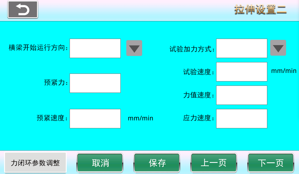
(2) Tensile Settings Two (L-2)
[Crosshead Start Direction] Click to set the crosshead start running direction after the test begins.
[Test Loading Method] Choose loading method according to test requirements: constant displacement speed, constant force speed, or constant stress speed.
[Preload] Force applied before loading to enhance connection reliability and tightness, preventing gaps or relative slip between connectors after loading.
[Preload Speed] Preload speed refers to the speed at which the fixture or sample is clamped before testing by setting clamping speed and force to achieve a stable clamping state with the testing machine contact surface.
[Test Speed] Speed during the test.
[Force Rate] Change of force value per unit time, unit is N/s.
[Stress Rate] Change of stress per unit time, unit is MPa/s.
[Force Closed-Loop Parameter Adjustment] PID parameter adjustment during constant force loading.
[Next Page] Turn to next page.
[Cancel] Cancel input settings and revert to the values before setting.
[Previous Page] Turn to previous page.
[Save] After modifying parameters, click save. The system will use the modified values by default on next startup (otherwise changes will not be saved on shutdown).
L-2
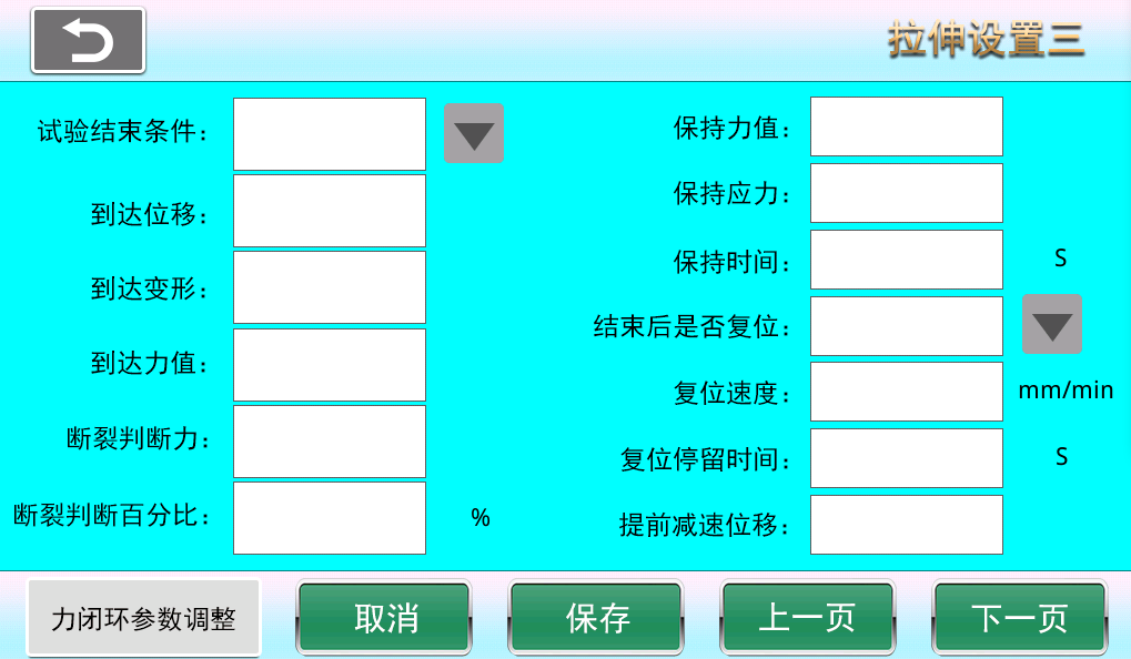
(3) Tensile Settings Three (L-3)
[Test End Conditions] Reach displacement, reach deformation, reach force value, fracture, force hold, stress hold.
[Reach Displacement] Test ends when the set displacement value is reached.
[Reach Deformation] Test ends when the set deformation value is reached.
[Reach Force Value] Test ends when the set force value is reached.
[Fracture Judgment Force] The system judges fracture only after the applied force exceeds the fracture judgment force; otherwise, if the force does not exceed this value, the system considers the sample to be in a jitter interference period and does not judge fracture.
[Fracture Judgment Percentage] After the applied force exceeds the fracture judgment force and reaches a peak, due to force drop during fracture, when the force drops to a percentage of the peak value (e.g., peak force 100N, force drops to 80N), the system considers the sample fractured; this percentage is the fracture judgment percentage (e.g., 80%).
[Hold Force] Hold force value set during constant force hold test.
[Hold Stress] Stress value maintained under constant stress.
[Hold Time] Duration of hold during force hold test.
[Reset After End Whether the crosshead resets to the test start position after the test ends.
[Reset Speed] Speed of crosshead return.
[Reset Dwell Time] Time the crosshead stays before resetting after test ends.
[Advance Deceleration Displacement] Displacement when the crosshead is about to reach the test start position during reset.
[Force Closed-Loop Parameter Adjustment] PID parameter adjustment during force hold test.
[Next Page] Turn to next page.
[Cancel] Cancel input settings and revert to the values before setting.
[Previous Page] Turn to previous page.
[Save] After modifying parameters, click save. The system will use the modified values by default on next startup (otherwise changes will not be saved on shutdown).
L-3
( 4) Tensile Settings Four (L-4)
[Test Result Selection] Check the corresponding boxes for the test results you need.
[Save] After modifying parameters, click save. The system will use the modified values by default on next startup (otherwise changes will not be saved on shutdown).
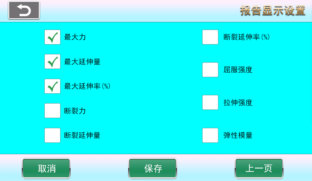
L-4
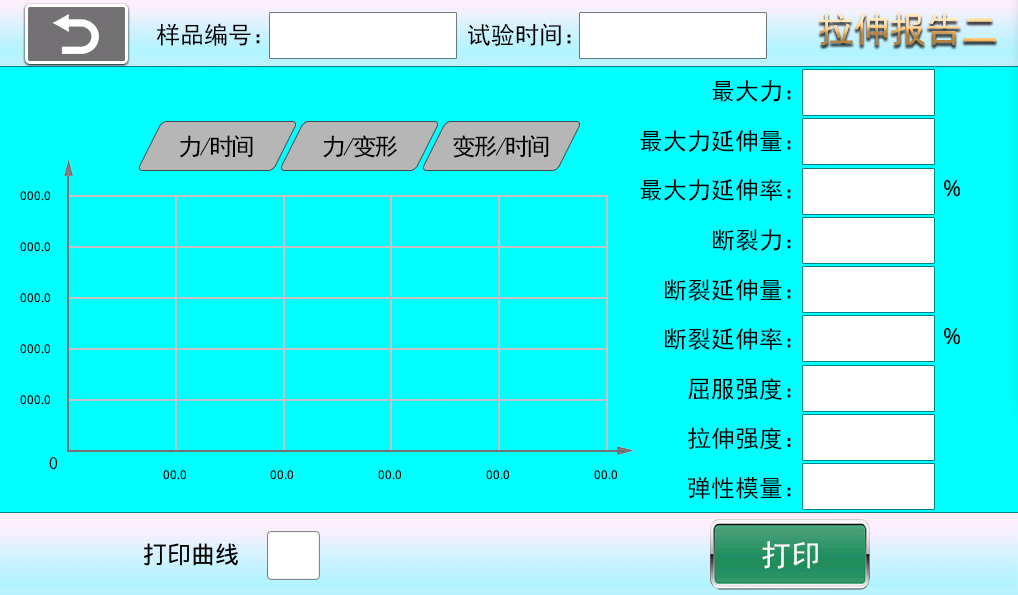
(5) Tensile Test Report (L-5)
[Test Number] Current page test number.
[Test Time] Test time on the current page, based on the end of the last sample test.
[Next Page] Flip to next page.
[Previous Page] Flip to previous page.
[Single Delete] Each deletion starts from the last test and deletes upwards, only one test result can be deleted at a time. This deletion can only delete data on the current page; historical pages cannot be deleted. When the system stores 50 pages of test results, it automatically overwrites from the first page.
[Delete All] Delete all results on the current page. (This deletion can only delete data on the current page; historical pages cannot be deleted. When the system stores 50 pages of test results, it automatically overwrites from the first page.)
[View Curve] Click any test data, then click View Curve to enter the single sample test result and curve.
[Print] Print all sample test results on the current page.
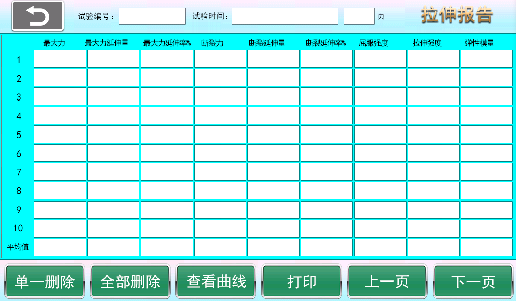
L-5
(6) Tensile test single sample report curve interface (L-6).
[Sample Number] Single sample test number.
[Test Time] Test time for a single sample test.
[Force/Time] View force/time curve.
[Force/Deformation] View force/deformation curve.
[Deformation/Time] View deformation/time curve.
[Print Curve] If checked, the current curve and sample test results will be displayed when printing. If unchecked, only the single sample test results will be printed.
[Print] Print single sample test results and curve.
L-6
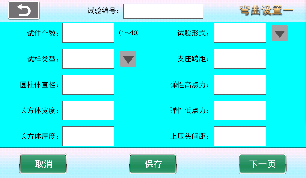
1.7, (1) Bending test settings (W-1).
[Number of Specimens] Select the number of specimens from 1 to 10. The test result interface will display the number of specimens per page after testing.
[Test Type] Three-point bending, four-point bending tests.
[Sample Type] You can choose cylinder, rectangular prism, or irregular body.
[Support Span] Distance between two end supports.
[Cylinder Diameter] Diameter of the cylinder.
[Rectangular Prism Width] Width of the rectangular block.
[Rectangular Block Thickness] Thickness of the rectangular block.
[Elastic Peak Force] Peak force value in the elastic stage.
[Elastic Low Force] Low force value in the elastic stage.
[Distance Between Upper Press Heads] Distance between two upper press heads (four-point bending).
[Next Page] Turn to next page.
[Cancel] Cancel input settings and revert to the values before setting.
[Save] After modifying parameters, click save. The system will use the modified values by default on next startup (otherwise changes will not be saved on shutdown).
W-1
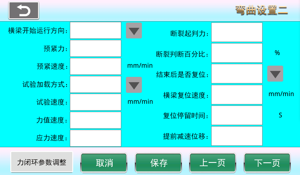
(2) Bending settings two (W-2).
[Crosshead Start Direction] Click to set the crosshead start running direction after the test begins.
[Preload] Force applied before loading to enhance connection reliability and tightness, preventing gaps or relative slip between connectors after loading.
[Preload Speed] Preload speed refers to the speed at which the fixture or sample is clamped before testing by setting clamping speed and force to achieve a stable clamping state with the testing machine contact surface.
[Test Loading Method] Choose loading method according to test requirements: constant displacement speed, constant force speed, or constant stress speed.
[Test Speed] Speed during the test.
[Force Rate] Change of force value per unit time, unit is N/s.
[Stress Rate] Change of stress per unit time, unit is MPa/s.
[Fracture Judgment Force] The system judges fracture only after the applied force exceeds the fracture judgment force; otherwise, if the force does not exceed this value, the system considers the sample to be in a jitter interference period and does not judge fracture.
[Fracture Judgment Percentage] After the applied force exceeds the fracture judgment force and reaches a peak, due to force drop during fracture, when the force drops to a percentage of the peak value (e.g., peak force 100N, force drops to 80N), the system considers the sample fractured; this percentage is the fracture judgment percentage (e.g., 80%).
[Reset After Completion] Whether the crossbeam resets to the starting position after the test ends.
[Reset Speed] Speed of crosshead return.
[Reset Dwell Time] Time the crosshead stays before resetting after test ends.
[Advance Deceleration Displacement] Displacement when the crosshead is about to reach the test start position during reset.
[Force Closed-Loop Parameter Adjustment] PID parameter adjustment during constant force loading test.
[Next Page] Flip to next page.
[Previous Page] Flip to previous page.
[Cancel] Cancel input settings and revert to the values before setting.
[Save] After modifying parameters, click save. The system will use the modified values by default on next startup (otherwise changes will not be saved on shutdown).
W-2
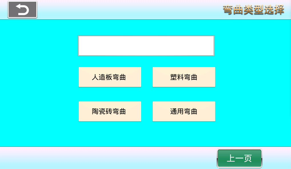
(3) Bending settings three (W-3).
[Artificial Board Bending] Suitable for GB/T17657-2022.
[Plastic Bending] Suitable for GB/T9341-2008/ISO178:2001.
[Ceramic Tile Bending] Suitable for GB/T3810.4-2016/ISO10545-4:2014,/GB/T39826-2021.
[General Bending] General bending tests.
[Previous Page] Turn to previous page.
W-3
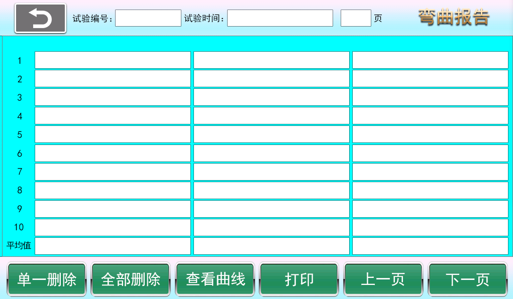
(4) Bending test report W-4.
[Test Number] Current page test number.
[Test Time] Test time on the current page, based on the end of the last sample test.
[Next Page] Flip to next page.
[Previous Page] Flip to previous page.
[Single Delete] Each deletion starts from the last test and deletes upwards, only one test result can be deleted at a time. This deletion can only delete data on the current page; historical pages cannot be deleted. When the system stores 50 pages of test results, it automatically overwrites from the first page.
[Delete All] Delete all results on the current page. (This deletion can only delete data on the current page; historical pages cannot be deleted. When the system stores 50 pages of test results, it automatically overwrites from the first page.)
[View Curve] Click any test data, then click View Curve to enter the single sample test result and curve.
[Print] Print all sample test results on the current page.
W-4
[Artificial Board Bending] Test Results: Maximum force, static bending strength, elastic modulus.
[Plastic Bending] Test Results: Bending stress, bending strain, bending modulus.
[Ceramic Tile Bending] Test Results: Failure load, failure strength, fracture modulus.
[General Bending ] Test Results: Maximum force, bending strength, elastic modulus.
[Bending Test Mode Switch] After selecting the test mode on the last bending settings interface, enter the test results interface, delete all current page historical data, then perform the test again. The test results will automatically refresh. The system will automatically save the current test mode on next startup.
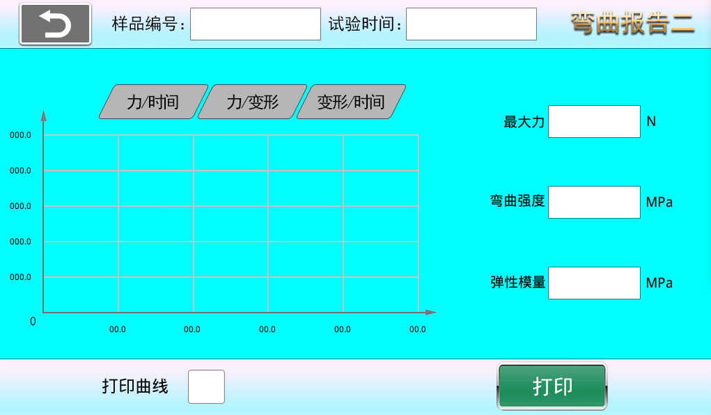
(5) Bending test single sample report curve interface (W-5).
[Sample Number] Single sample test number.
[Test Time] Test time for a single sample test.
[Force/Time] View force/time curve.
[Force/Deformation] View force/deformation curve.
[Deformation/Time] View deformation/time curve.
[Print Curve] If checked, the current curve and sample test results will be displayed when printing. If unchecked, only the single sample test results will be printed.
[Print] Print single sample test results and curve.
W-5
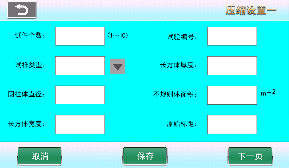
1.8, (1) Compression test settings (Y-1).
[Number of Specimens] Select the number of specimens from 1 to 10. The test result interface will display the number of specimens per page after testing.
[Test Number] The number of each page in each group or test result.
[Sample Type] You can choose cylinder, rectangular prism, or irregular body.
[Rectangular Prism Thickness/Length] Specimen length, or thickness for some specimens.
[Cylinder Diameter] Diameter of the cylinder.
[Irregular Body Area] For irregular bodies where length or width cannot be measured, the specimen strength is calculated using the irregular body area.
[Rectangular Prism Width] Sample width.
[Sample Gauge Length] At any moment during the test, the length of the parallel section used to measure sample elongation.
[Next Page] Turn to next page.
[Cancel] Cancel input settings and revert to the values before setting.
[Save] After modifying parameters, click save. The system will use the modified values by default on next startup (otherwise changes will not be saved on shutdown).
3-1.
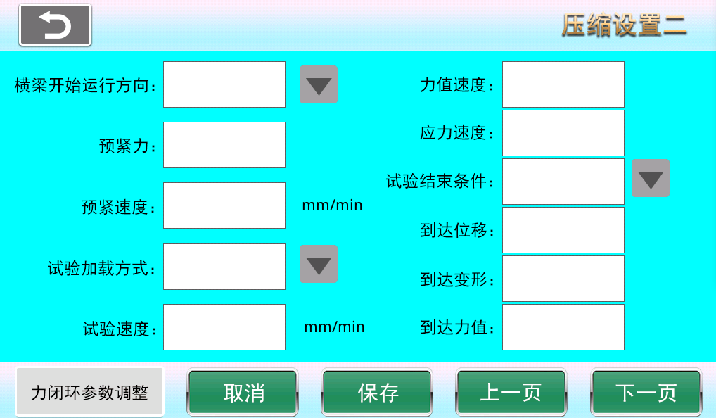
(2) Compression settings two (Y-2).
[Crosshead Start Direction] Click to set the crosshead start running direction after the test begins.
[Test Loading Method] Choose loading method according to test requirements: constant displacement speed, constant force speed, or constant stress speed.
[Preload] Force applied before loading to enhance connection reliability and tightness, preventing gaps or relative slip between connectors after loading.
[Preload Speed] Preload speed refers to the speed at which the fixture or sample is clamped before testing by setting clamping speed and force to achieve a stable clamping state with the testing machine contact surface.
[Test Speed] Speed during the test.
[Force Rate] Change of force value per unit time, unit is N/s.
[Stress Rate] Change of stress per unit time, unit is MPa/s.
[Test End Conditions] Reach displacement, reach deformation, reach force value, fracture, force hold, stress hold.
[Reach Displacement] Test ends when the set displacement value is reached.
[Reach Deformation] Test ends when the set deformation value is reached.
[Reach Force Value] Test ends when the set force value is reached.
[Force Closed-Loop Parameter Adjustment] PID parameter adjustment during constant force loading.
[Next Page] Turn to next page.
[Cancel] Cancel input settings and revert to the values before setting.
[Previous Page] Turn to previous page.
[Save] After modifying parameters, click save. The system will use the modified values by default on next startup (otherwise changes will not be saved on shutdown).
Y-2
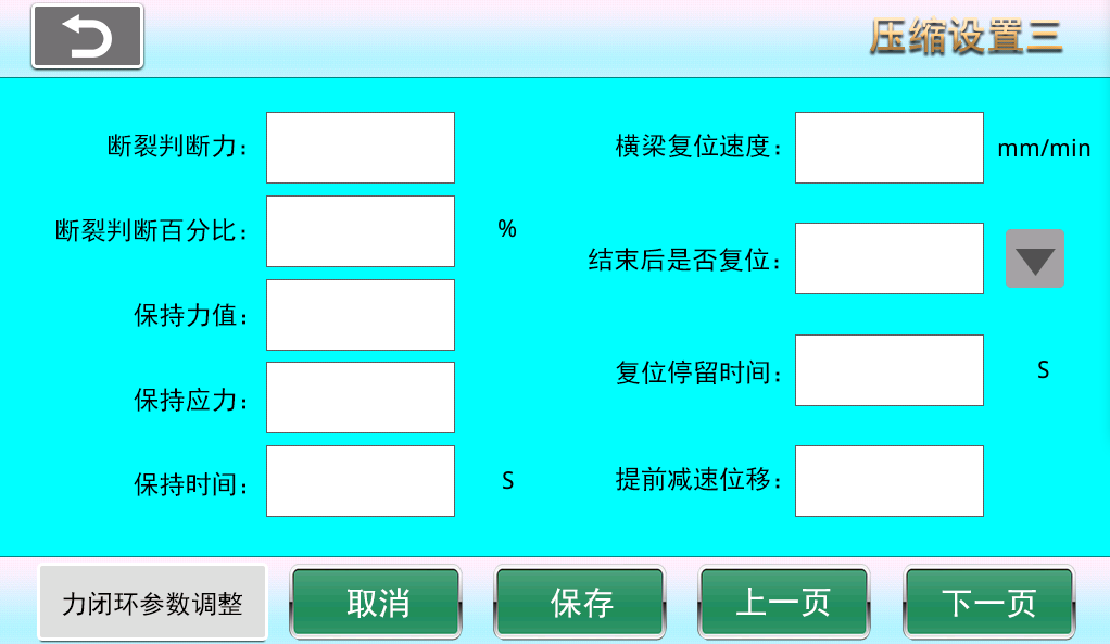
(3). Compression settings three (Y-3).
[Fracture Judgment Force] The system judges fracture only after the applied force exceeds the fracture judgment force; otherwise, if the force does not exceed this value, the system considers the sample to be in a jitter interference period and does not judge fracture.
[Fracture Judgment Percentage] After the applied force exceeds the fracture judgment force and reaches a peak, due to force drop during fracture, when the force drops to a percentage of the peak value (e.g., peak force 100N, force drops to 80N), the system considers the sample fractured; this percentage is the fracture judgment percentage (e.g., 80%).
[Hold Force] Hold force value set during constant force hold test.
[Hold Stress] Stress value maintained under constant stress.
[Hold Time] Duration of hold during force hold test.
[Crossbeam Reset Speed] Speed when the crossbeam returns.
[Reset After End Whether the crosshead resets to the test start position after the test ends.
[Reset Speed] Speed when the crossbeam returns.
[Reset Dwell Time] Time the crossbeam stays before resetting after test completion.
[Advance Deceleration Displacement] Displacement when the crosshead is about to reach the test start position during reset.
[Force Closed-Loop Parameter Adjustment] PID parameter adjustment during force hold test.
[Next Page] Turn to next page.
[Cancel] Cancel input settings and revert to the values before setting.
[Previous Page] Turn to previous page.
[Save] After modifying parameters, click save. The system will use the modified values by default on next startup (otherwise changes will not be saved on shutdown).
Y-3
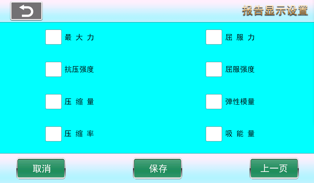
(4) Compression report display settings (Y-4).
Test result selection] Check the corresponding boxes for the test results you need.
[Save] After modifying parameters, click save. The system will use the modified values by default on next startup (otherwise changes will not be saved on shutdown).
Y-4
(5) Compression test report (Y-5).
[Test Number] Current page test number.
[Test Time] Test time on the current page, based on the end of the last sample test.
[Next Page] Flip to next page.
[Previous Page] Flip to previous page.
[Single Delete] Each deletion starts from the last test and deletes upwards, only one test result can be deleted at a time. This deletion can only delete data on the current page; historical pages cannot be deleted. When the system stores 50 pages of test results, it automatically overwrites from the first page.
[Delete All] Delete all results on the current page. (This deletion can only delete data on the current page; historical pages cannot be deleted. When the system stores 50 pages of test results, it automatically overwrites from the first page.)
[View Curve] Click any test data, then click View Curve to enter the single sample test result and curve.
[Print] Print all sample test results on the current page.

Y-5
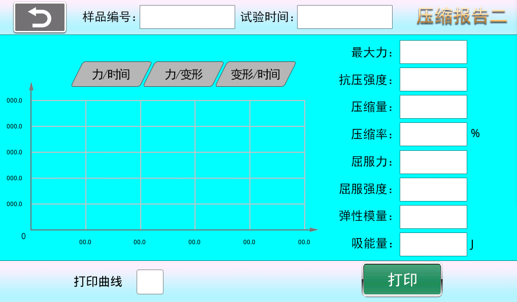
(6) Compression Test Single Sample Report Curve Interface (Y-6)
[Sample Number] Single sample test number.
[Test Time] Test time for a single sample test.
[Force/Time] View force/time curve.
[Force/Deformation] View force/deformation curve.
[Deformation/Time] View deformation/time curve.
[Print Curve] If checked, the current curve and sample test results will be displayed when printing. If unchecked, only the single sample test results will be printed.
[Print] Print single sample test results and curve.
Y-6
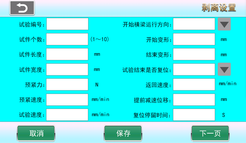
1.9, (1) Peeling Setting One (B-1)
[Test Number] The number of each page in each group or test result.
[Number of Specimens] Select the number of specimens from 1 to 10. The test result interface will display the number of specimens per page after testing.
[Crosshead Start Direction] Click to set the crosshead start running direction after the test begins.
[Specimen Length] Length of the specimen
[Specimen Width] Width of the specimen
[Start Deformation] Start calculating deformation during peeling
[End Deformation] End calculating deformation during peeling
[Test Loading Method] Choose loading method according to test requirements: constant displacement speed, constant force speed, or constant stress speed.
[Preload] Force applied before loading to enhance connection reliability and tightness, preventing gaps or relative slip between connectors after loading.
[Preload Speed] Preload speed refers to the speed at which the fixture or sample is clamped before testing by setting clamping speed and force to achieve a stable clamping state with the testing machine contact surface.
[Test Speed] Speed during the test.
[Reset After End Whether the crosshead resets to the test start position after the test ends.
[Reset Speed] Speed of crosshead return.
[Reset Dwell Time] Time the crosshead stays before resetting after test ends.
[Advance Deceleration Displacement] Displacement when the crosshead is about to reach the test start position during reset.
[Next Page] Turn to next page.
[Cancel] Cancel input settings and revert to the values before setting.
[Save] After modifying parameters, click save. The system will use the modified values by default on next startup (otherwise changes will not be saved on shutdown).
Note: The peeling test ends when the displacement has covered the specimen length, but the peeling force calculation is from start deformation to end deformation.
B-1
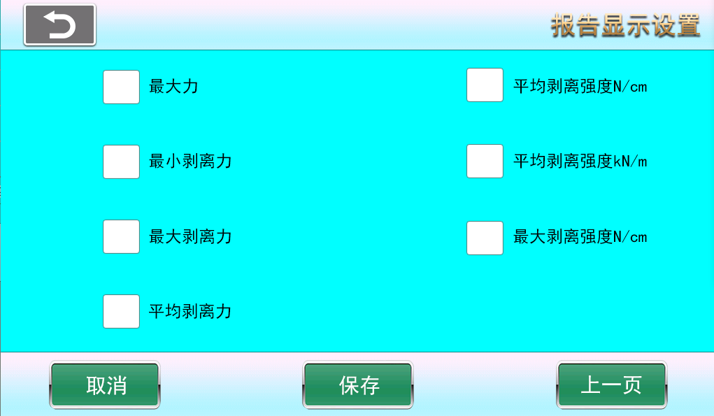
(2) Peeling Report Display Settings (B-2)
Test result selection] Check the corresponding boxes for the test results you need.
[Save] After modifying parameters, click save. The system will use the modified values by default on next startup (otherwise changes will not be saved on shutdown).
B-2
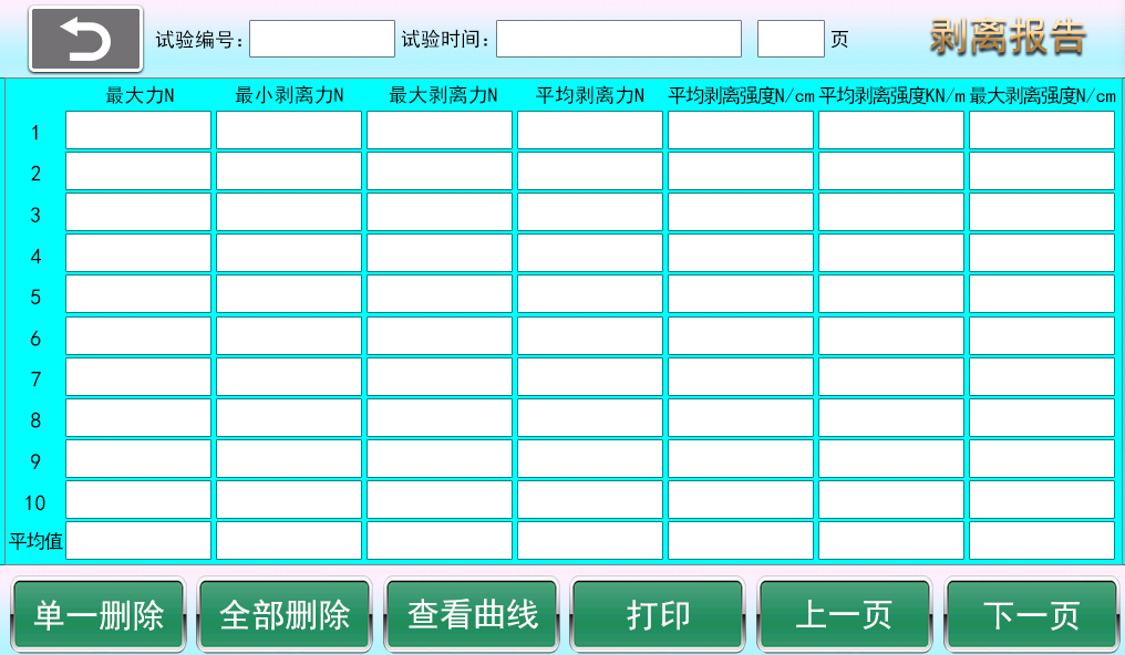
(3) Peeling Test Report (B-3)
[Test Number] Current page test number.
[Test Time] Test time on the current page, based on the end of the last sample test.
[Next Page] Flip to next page.
[Previous Page] Flip to previous page.
[Single Delete] Each deletion starts from the last test and deletes upwards, only one test result can be deleted at a time. This deletion can only delete data on the current page; historical pages cannot be deleted. When the system stores 50 pages of test results, it automatically overwrites from the first page.
[Delete All] Delete all results on the current page. (This deletion can only delete data on the current page; historical pages cannot be deleted. When the system stores 50 pages of test results, it automatically overwrites from the first page.)
[View Curve] Click any test data, then click View Curve to enter the single sample test result and curve.
[Print] Print all sample test results on the current page.
B-3
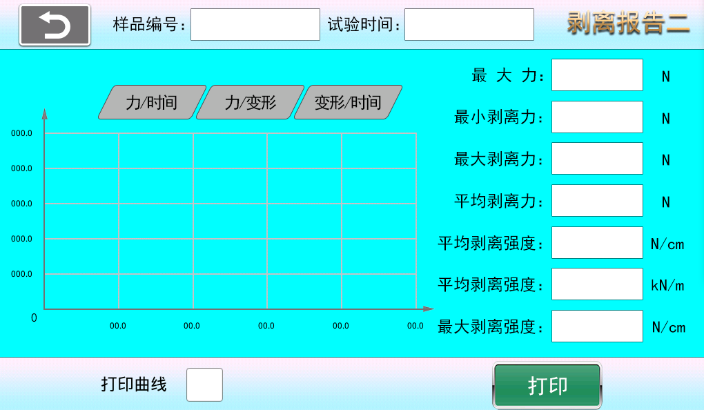
(4) Peeling Test Single Sample Report Curve Interface (B-4)
[Sample Number] Single sample test number.
[Test Time] Test time for a single sample test.
[Force/Time] View force/time curve.
[Force/Deformation] View force/deformation curve.
[Deformation/Time] View deformation/time curve.
[Print Curve] If checked, the current curve and sample test results will be displayed when printing. If unchecked, only the single sample test results will be printed.
[Print] Print single sample test results and curve.
B-4
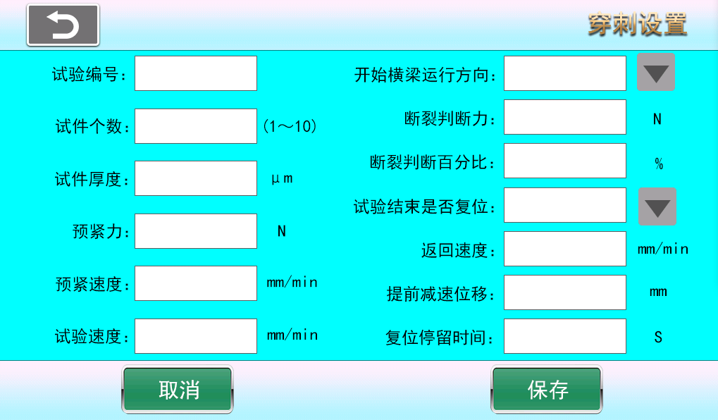
1.10 Puncture Setting (C-1)
[Test Number] The number of each page in each group or test result.
[Number of Specimens] Select the number of specimens from 1 to 10. The test result interface will display the number of specimens per page after testing.
[Crosshead Start Direction] Click to set the crosshead start running direction after the test begins.
[Preload] Force applied before loading to enhance connection reliability and tightness, preventing gaps or relative slip between connectors after loading.
[Preload Speed] Preload speed refers to the speed at which the fixture or sample is clamped before testing by setting clamping speed and force to achieve a stable clamping state with the testing machine contact surface.
[Test Speed] Speed during the test.
[Fracture Judgment Force] The system judges fracture only after the applied force exceeds the fracture judgment force; otherwise, if the force does not exceed this value, the system considers the sample to be in a jitter interference period and does not judge fracture.
[Fracture Judgment Percentage] After the applied force exceeds the fracture judgment force and reaches a peak, due to force drop during fracture, when the force drops to a percentage of the peak value (e.g., peak force 100N, force drops to 80N), the system considers the sample fractured; this percentage is the fracture judgment percentage (e.g., 80%).
[Reset After Completion] Whether the crossbeam resets to the starting position after the test ends.
[Return Speed] Speed of crosshead return.
[Reset Dwell Time] Time the crosshead stays before resetting after test ends.
[Advance Deceleration Displacement] Displacement when the crosshead is about to reach the test start position during reset.
[Cancel] Cancel input settings and revert to the values before setting.
[Save] After modifying parameters, click save. The system will use the modified values by default on next startup (otherwise changes will not be saved on shutdown).
C-1
(2) Puncture Test Report (C-2)
[Test Number] Current page test number.
[Test Time] Test time on the current page, based on the end of the last sample test.
[Next Page] Flip to next page.
[Previous Page] Flip to previous page.
[Single Delete] Each deletion starts from the last test and deletes upwards, only one test result can be deleted at a time. This deletion can only delete data on the current page; historical pages cannot be deleted. When the system stores 50 pages of test results, it automatically overwrites from the first page.
[Delete All] Delete all results on the current page. (This deletion can only delete data on the current page; historical pages cannot be deleted. When the system stores 50 pages of test results, it automatically overwrites from the first page.)
[View Curve] Click any test data, then click View Curve to enter the single sample test result and curve.
[Print] Print all sample test results on the current page.

C-2
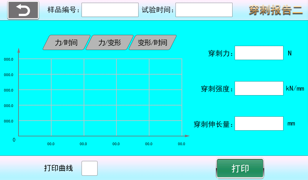
(3) Puncture Test Single Sample Report Curve Interface (C-3)
[Sample Number] Single sample test number.
[Test Time] Test time for a single sample test.
[Force/Time] View force/time curve.
[Force/Deformation] View force/deformation curve.
[Deformation/Time] View deformation/time curve.
[Print Curve] If checked, the current curve and sample test results will be displayed when printing. If unchecked, only the single sample test results will be printed.
[Print] Print single sample test results and curve.
C-3
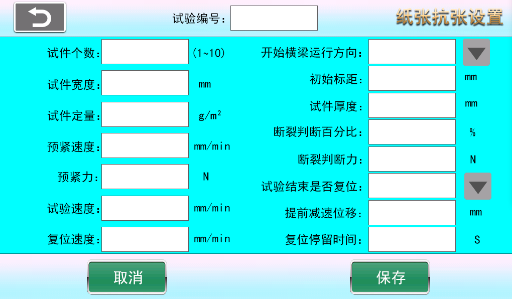
1.1, (1) Paper Tensile Setting (Z-1)
[Test Number] The number of each page in each group or test result.
[Number of Specimens] Select the number of specimens from 1 to 10. The test result interface will display the number of specimens per page after testing.
[Start Crossbeam Running Direction] Click to set the crosshead start running direction after the test begins.
[Preload] Force applied before loading to enhance connection reliability and tightness, preventing gaps or relative slip between connectors after loading.
[Preload Speed] Preload speed refers to the speed at which the fixture or sample is clamped before testing by setting clamping speed and force to achieve a stable clamping state with the testing machine contact surface.
[Specimen Width] Width of the specimen
[Initial Gauge Length] Specimen gauge length before starting the test
[Specimen Thickness] Thickness of the specimen
[Specimen Basis Weight] Mass per unit area
[Test Speed] Speed during the test.
[Fracture Judgment Force] The system judges fracture only after the applied force exceeds the fracture judgment force; otherwise, if the force does not exceed this value, the system considers the sample to be in a jitter interference period and does not judge fracture.
[Fracture Judgment Percentage] After the applied force exceeds the fracture judgment force and reaches a peak, due to force drop during fracture, when the force drops to a percentage of the peak value (e.g., peak force 100N, force drops to 80N), the system considers the sample fractured; this percentage is the fracture judgment percentage (e.g., 80%).
[Reset After Completion] Whether the crossbeam resets to the starting position after the test ends.
[Reset Speed] Speed of crosshead return.
[Reset Dwell Time] Time the crosshead stays before resetting after test ends.
[Advance Deceleration Displacement] Displacement when the crosshead is about to reach the test start position during reset.
[Cancel] Cancel input settings and revert to the values before setting.
[Save] After modifying parameters, click save. The system will use the modified values by default on next startup (otherwise changes will not be saved on shutdown).
Z-1
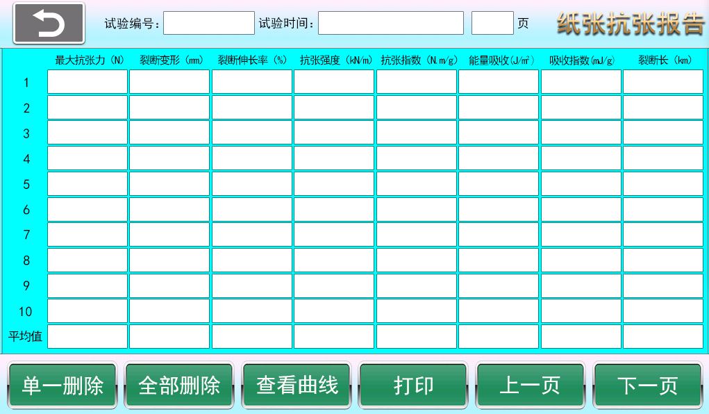
(2) Paper Tensile Test Report (Z-2)
[Test Number] Current page test number.
[Test Time] Test time on the current page, based on the end of the last sample test.
[Next Page] Flip to next page.
[Previous Page] Flip to previous page.
[Single Delete] Each deletion starts from the last test and deletes upwards, only one test result can be deleted at a time. This deletion can only delete data on the current page; historical pages cannot be deleted. When the system stores 50 pages of test results, it automatically overwrites from the first page.
[Delete All] Delete all results on the current page. (This deletion can only delete data on the current page; historical pages cannot be deleted. When the system stores 50 pages of test results, it automatically overwrites from the first page.)
[View Curve] Click any test data, then click View Curve to enter the single sample test result and curve.
[Print] Print all sample test results on the current page.
Z-2
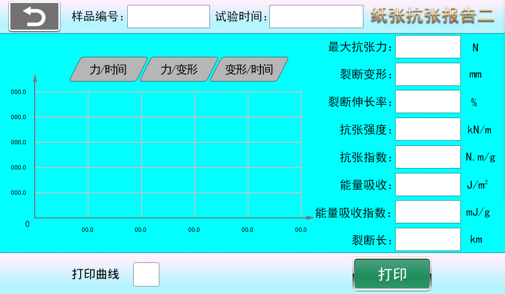
(3) Paper Tensile Test Single Sample Report Curve Interface (Z-3)
[Sample Number] Single sample test number.
[Test Time] Test time for a single sample test.
[Force/Time] View force/time curve.
[Force/Deformation] View force/deformation curve.
[Deformation/Time] View deformation/time curve.
[Print Curve] If checked, the current curve and sample test results will be displayed when printing. If unchecked, only the single sample test results will be printed.
[Print] Print single sample test results and curve.
Z-3
- Calibration
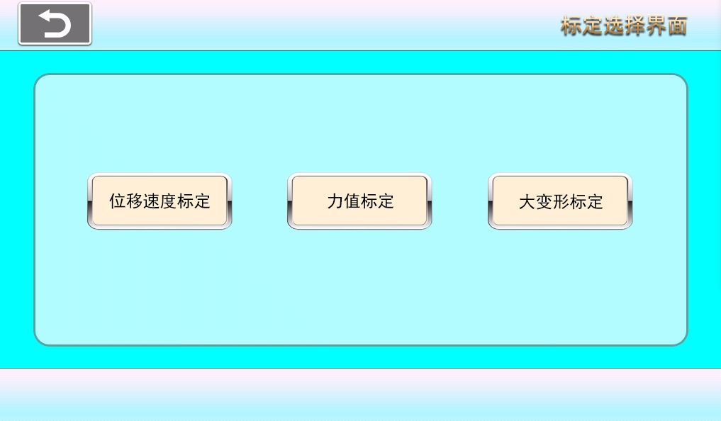
2.1 Calibration Selection (2-1) (The following calibration interface is provided for professional maintenance personnel; operating users can ignore)
Click the "Calibration" button in the main menu, enter the password "******" to enter the calibration selection interface as shown below
Calibration data is pre-calibrated by the manufacturer before shipment and does not need modification. Maintenance personnel can calibrate and modify.
[Displacement and Speed Calibration] Displacement and speed calibration; speed is calibrated simultaneously with displacement.
[Force Calibration] Calibration of the force sensor.
[Large Deformation Calibration] Calibration of the large deformation extensometer.
2-1
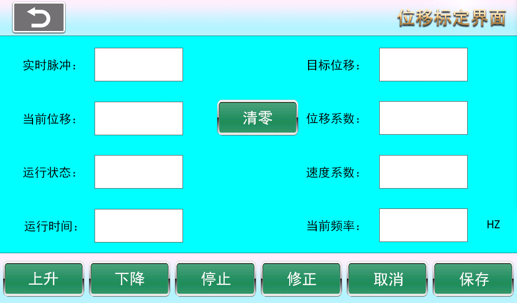
2.2 Displacement and Speed Calibration:
Displacement and speed calibration as shown in the figure (2-2)
2-2
[Real-time Pulse] Real-time pulse count from the encoder or internal timer when moving up or down.
[Current Stroke] Real-time displacement amount
[Operating Status] Rising, descending, stopped
[Operating Time] Real-time operating time since the motor started running.
[Target Stroke] Displacement traveled by the motor from start to stop.
[Displacement Coefficient] Displacement coefficient value (automatically generated after correction)
[Speed Coefficient] Speed coefficient value (automatically generated after correction)
[Current Frequency] Change the "Current Frequency" to adjust the motor speed.
Stroke calibration process: First click "Reset" before calibration, then click "Up" or "Down" to let the press plate move a sufficient displacement, input this displacement value into the target stroke, then click "Correct", finally click save to complete the "Stroke Speed Calibration".
[Save] After calibration, click the "Save" button to save the data, otherwise the data will not be saved after the next power on.
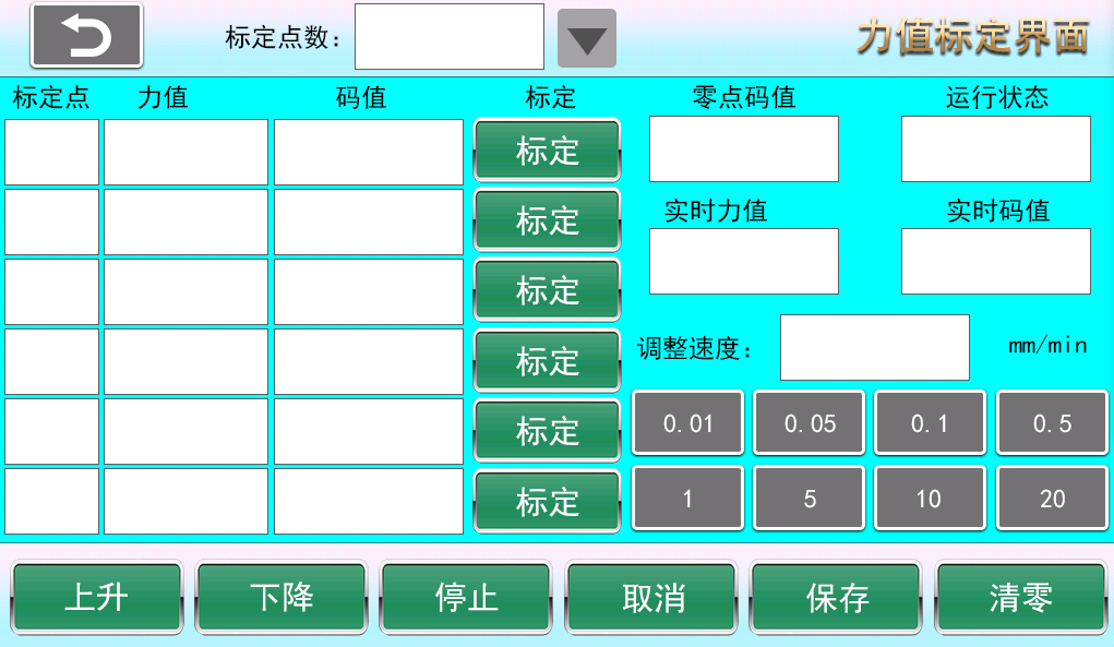
2.3 Force Calibration:
Force calibration as shown in the figure (2-3)
[Number of Calibration Points] Number of force calibration points, up to 6 points can be calibrated.
[Zero Code Value] Code value at zero point.
[Real-time Force Value] Real-time value of the force sensor.
[Real-time Code Value] Code value corresponding to the force value used as a real-time variable for force calibration.
[Adjust Speed] Adjust speed when motor is rising or descending.
Force calibration process: First, select the number of calibration points needed, such as 5 points or 6 points, then modify the force value for each calibration point below the force value section. Click reset to ensure both the standard sensor and the sensor to be calibrated are at zero load. Click adjust to start at a speed of 10mm/min or another speed. Click up or down to slowly load the sensor. When approaching the first calibration point, click a smaller adjustment speed to slowly reach the first calibration point. Then click the "Calibrate" button behind it to complete the first calibration point. Repeat this process for all calibration points. After all calibration points are completed, click save to finish the calibration.
[Save] After calibration, click the "Save" button to save the data, otherwise the data will not be saved after the next power on.
2-3
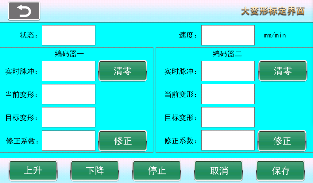
2.4 Large Deformation Calibration:
Large deformation calibration as shown in the figure (2-4)
[Status] Motor status: up, down, stop
[Speed] Motor speed
[Encoder 1] When calibrating the first large deformation path, as the motor moves up or down, input the actual displacement into the corresponding target deformation input box under Encoder 1, then click "Correct" to complete the calibration of the first encoder.
[Encoder 2] When calibrating the second large deformation path, as the motor moves up or down, input the actual displacement into the corresponding target deformation input box under Encoder 2, then click "Correct" to complete the calibration of the second encoder.
[Save] After calibration, click the "Save" button to save the data, otherwise the data will not be saved after the next power on.
2-4
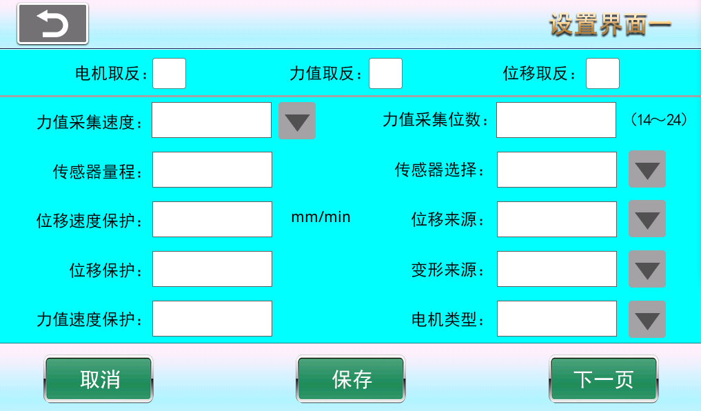
- Configuration (3-1)
[Motor Reverse] Reverse the motor rotation direction (reverse the crossbeam running direction, changing the motor rotation direction will affect all test modes).
[Force Value Reverse] When the test force value is negative, you need to change the force value to a positive integer, otherwise the test curve cannot be drawn and no test results will be produced. The force sensor polarity is reversed (changing the force polarity in the current test mode will not affect the force polarity in other test modes. For example, if "Tensile Test" is selected in the test selection interface, and the force polarity is reversed in the configuration interface, only the tensile test force polarity changes, and bending test, compression test, and other test modes remain unchanged).
[Displacement Reverse] When the test displacement is negative, you need to change the displacement to a positive integer, otherwise the test curve cannot be drawn and no test results will be produced. Displacement polarity can be reversed. If negative displacement appears after starting the test, you can check the displacement reverse option in the configuration interface to change the displacement polarity. (Changing displacement polarity in the current test mode will not affect displacement polarity in other test modes).
[Force Value Acquisition Speed] During the test process, the sensor feedbacks the real-time speed to the acquisition board when under load (no need to modify, factory preset).
[Force Value Acquisition Bits] Force acquisition accuracy setting. If the sensor range is large, for example above 2T, you can set the acquisition bits to 18 or 20 bits to increase the bit count and improve force accuracy. After modification, the force sensor needs to be recalibrated (modification prohibited for non-debug personnel).
[Sensor Range] Maximum sensor range. You can also input a value close to the sensor range to protect the sensor from being damaged by compression or tension.
[Sensor Selection] If one sensor cannot meet the test requirements, four sensors can be equipped to meet different tests. Each sensor must have displacement and force calibration completed and saved separately (modify with caution).
[Displacement Speed Protection] This is the speed protection for the motor crossbeam's up and down movement. If the speed exceeds the set value, the motor will stop running. If displacement speed protection occurs during the test and the test stops, no test results will be produced.
[Displacement Source] Displacement source is the method of displacement counting, generally internal counting or encoder counting. Servo motors select encoder counting, stepper motors select internal counting (modification prohibited for non-debug personnel).
[Displacement Protection] When the set displacement protection value is exceeded, the motor will stop running and the test will be interrupted (modify with caution).
[Deformation Source] Deformation source is generally displacement or large deformation. When not using a large deformation sensor, select displacement as the source (operate with caution).
[Force Value Speed Protection]
[Motor Type] Servo motor and stepper motor. If displacement source selects internal recording, it is best to choose stepper motor. Stepper motors have a slow acceleration process at startup. If the device is equipped with a servo motor, this is not necessary (modify with caution).
[Next Page] Turn to next page.
[Cancel] Cancel input settings and revert to the values before setting.
[Save] After modifying parameters, click save. The system will use the modified values by default on next startup (otherwise changes will not be saved on shutdown).
3-1.
3.2 Configuration Two (3-2)
[Force Unit] Modify force units to KN, N, Kg, Kgf, Ibf. Decimal places can be selected from 1 to 3.
[Displacement Unit] Modify displacement units to m, dm, cm, mm, in. Decimal places can be selected from 1 to 3.
[Deformation Unit] Modify deformation units to m, dm, cm, mm, in. Decimal places can be selected from 1 to 3.
[Strength Unit] Modify strength units to Pa, kPa, MPa, bar. Decimal places can be selected from 1 to 3.
[Zero Point Minimum Resolution] Change the sensitivity of force value drift when returning to zero point. This value should not be too large (generally 0 to 0.5, setting it will lose some accuracy). If not set, just set it to zero.
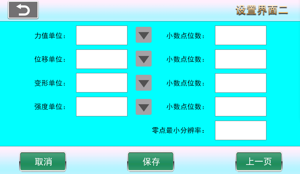
(3-2)
- Help (4-1)
Company Profile
Hebei Yinfeng Experimental Instrument Co., Ltd. is a high-tech enterprise dedicated to the research and development, production, and sales of experimental instruments. The company is headquartered in Hebei Province, relying on the strong industrial foundation and technological innovation resources in the Beijing Tianjin Hebei region. It is committed to providing high-precision and high reliability testing equipment and solutions for material testing, engineering quality control, scientific research experiments and other fields.


Customized Delivery Process
We provide customers with full-process services ranging from pre-sale consultation, customized solution design, equipment installation and commissioning to after-sale technical support.
Online Communication
Provide Custom Drawings
Merchant Quotation
Sign A Contract
Processing And Production
Packaging And Distribution
Confirm Receipt Of Goods
Successful Transaction
Previous:
Ceramic Tile Fracture Modulus Flexural Testing Machine
If you need customized products, Contact US !
Share to


Category
Tag list
Request a Quote
We will contact you within one working day. Please pay attention to your email.
Related Products
Content update in progress
Message
We will contact you within one business day. Please note your email address.
Fast navigation
Contact Us
Whatsapp/Tel: +86-15931715356,+86 16631790555
E-mail: info@cnhblabequipment.com
Add: Chengnan Industrial Zone, Xian County, Cangzhou City, Hebei Province