



- Product Describe
-
BZYS-4212 Surface Vibration Compactor It is a testing instrument used to determine the maximum dry density of non-cohesive, freely draining coarse-grained soils and very coarse-grained soils (including rockfill) by means of surface vibration compaction. This test is suitable for coarse-grained soils, particularly those with high permeability for which the maximum dry density and optimum moisture content cannot be determined or are difficult to determine using conventional compaction tests.
The surface vibration compactor complies with China’s transportation industry standard “Highway Geotechnical Testing Procedures” JTG 3430–2020 and is designated as the primary method for determining the maximum dry density of cohesive coarse-grained soils and very coarse-grained soils. The surface vibration compaction method simulates vibration rolling conditions, is easy to operate, and minimizes sample segregation during compaction. Therefore, TO133–2019 recommends giving priority to the surface vibration compaction method; moreover, this method can also be applied to specimen preparation for large triaxial tests on coarse-grained soils, permeability tests, concrete material tests, and base-course material tests, among other applications.
Main Technical Parameters
1 Power supply voltage 380V 2 Lift Power 370W 3 Vibration power 0.75-2.2KW 4 Vibration frequency 30HZ-50HZ 5 Excitation force 10-80KN 6 Test Duration 0–999 seconds, arbitrarily set 7 Static pressure exerted by the rammer on the specimen surface 18Kpa 8 Test cylinder specifications Iron large cylinder: 280 mm × 230 mm; sleeve: 280 mm × 170 mm. Iron small cylinder: 152 mm × 170 mm; sleeve: 152 mm × 65 mm. 9 External dimensions (length × width × height) 610×480×1460mm Working Principle
1. The vibratory compaction plate applies vertical vibrations to the specimen surface, with the vibration propagating from top to bottom. As a result of particle angularity being sheared and fractured, the particles rearrange themselves and settle into stable positions that conform to the standard conditions specified in geotechnical testing protocols, thereby achieving compaction of the soil mass.
Test Procedure for the Surface Vibration Compaction Apparatus, Step 1: Install the appropriate test cylinder, secure the cylinder firmly, and take an appropriate amount of soil sample. Use the specified tools to place the sample into the test cylinder and roughly level the surface of the specimen.
2. Please ensure that the three-phase power supply is properly connected and that the phase sequence is correct, and that the power indicator light on the controller panel is illuminated.
3. Press the up, stop, and down buttons on the controller; the vibration motor and all counterweight components should move smoothly and freely.
4. If, when the raise switch is pressed, the vibrator moves downward, or if, when the lower switch is pressed, the vibrator moves upward, the power supply wires must be reversed. Otherwise, both the upper and lower limit switches will fail to operate, which can easily damage the machine.
5. Press the descent button to lower the large sliding sleeve, which in turn drives the vibration plate and tamping plate downward. When the tamping plate contacts the loose soil sample, the large sliding sleeve continues to descend until its lower end face is 15–25 mm from the flange of the vibration plate, at which point press the stop button to halt the descent of the large sliding sleeve.
6. Set the timer on the controller to 6 minutes, then press the vibration switch to start the vibration. The timer will display the duration of the vibration, and the vibrating plate will automatically stop after 6 minutes.
7. Press the raise button to drive the vibration plate and rammer upward until the upper surface of the limit block is 15–25 mm below the gearbox, then press the stop button to halt the upward movement of the large slide.
8. Add the second soil sample in accordance with the test procedure, and repeat the above steps twice; at that point, one specimen is considered to have completed vibration compaction.
9. Remove the test cylinder, place a straight steel ruler across the diameter of the cylinder, measure the data according to the procedure, and then weigh it again.
10. Data organization and calculation.
Precautions
1. Surface Vibration Compactor During installation, it is recommended to pour a concrete base to ensure stable machine operation; place an 8–10 mm rubber pad beneath the concrete base to reduce vibration.
2. Surface Vibration Compactor An “Emergency Stop” button is provided; when the machine is performing any operation, pressing this button will immediately halt all movements.
3. When releasing the “Emergency Stop” button, rotate it 90° in the direction indicated by the arrow on top of the button, then release; the “Emergency Stop” button will then be released.
4. During the vibration compaction process, if the suspension screw of the machine does not descend far enough, empty vibration may occur. In this case, simply press the “Descend” button once; once the screw has reached the desired position, press the “Stop” button.
5. When tightening the hood bolts on the vibration plate, thread-locking adhesive was applied to all of them; if a failure occurs and the bolts need to be removed, a small amount of “914” adhesive should be applied to prevent the bolts from backing out.
6. Surface Vibration Compactor Equipped with limit switches, the machine will automatically stop if the vibration reaches its upper or lower extreme without the “Stop” button being pressed.
7. During normal operation, when the large sliding sleeve has risen 20 mm above the top dead center, press the “Stop” button; when descending and the hammer head has already contacted the soil sample, press the “Stop” button again once the large sliding sleeve has descended an additional 50–60 mm.
8. Regularly apply lubricating oil and grease to sliding parts and areas equipped with grease nipples.
9. Prior to each operational test, the exterior surface of the upright column shall be cleaned of dust, and mechanical oil (No. 20) shall be applied.
Company Profile
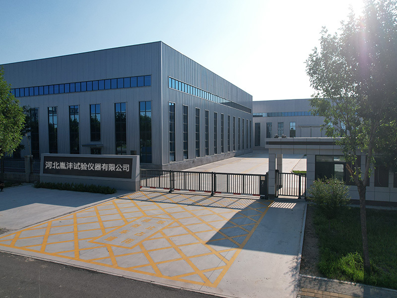
Hebei Yinfeng Experimental Instrument Co., Ltd. is a high-tech enterprise dedicated to the research and development, production, and sales of experimental instruments. The company is headquartered in Hebei Province, relying on the strong industrial foundation and technological innovation resources in the Beijing Tianjin Hebei region. It is committed to providing high-precision and high reliability testing equipment and solutions for material testing, engineering quality control, scientific research experiments and other fields.



Customized Delivery Process
We provide customers with full-process services ranging from pre-sale consultation, customized solution design, equipment installation and commissioning to after-sale technical support.
Online Communication
Provide Custom Drawings
Merchant Quotation
Sign A Contract
Processing And Production
Packaging And Distribution
Confirm Receipt Of Goods
Successful Transaction
Surface Vibration Compaction Tester
If you need customized products, Contact US !
Share to


Category
Tag list
Request a Quote
We will contact you within one working day. Please pay attention to your email.
Related Products
Content update in progress
Message
We will contact you within one business day. Please note your email address.
Fast navigation
Contact Us
Whatsapp/Tel: +86-15931715356,+86 16631790555
E-mail: qcj@cnhblabequipment.com
Add: Chengnan Industrial Zone, Xian County, Cangzhou City, Hebei Province

Online Message