



- Product Describe
-
Overview
The geosynthetic vertical permeability testing apparatus is a horizontal constant-head permeability tester designed and manufactured in accordance with the requirements of the newly issued Ministry of Transport standards: “Test Procedures for Geosynthetics in Highway Engineering” JTG E50-2006, GB/T 15789-2016 Method B, and SL/T 235-2012. It is suitable for conducting vertical permeability tests on various permeable geotextiles and composite geotextiles under constant head conditions.
Principle
Water flow velocity (mm/s) under a unit hydraulic gradient in the direction perpendicular to the plane of the geotextile
Main Technical Parameters
1 Maximum hydraulic head difference 150 mmH₂O (adjustable) 2 Gripper inner diameter Φ50±0.5mm 3 Maximum specimen thickness 20mm 4 Time counter 0–99.99 s 5 Thermometer range 0–50°C (accuracy: 0.1°C) 6 Power supply AC 220V ±10%, 50 Hz 7 External dimensions 800×720×2100mm 8 Weight 95Kg Instrument Structure
The instrument consists of a housing, a container, a holder, control piping, and a control circuit, among other components. (See Figure 1 for the external view.)
1. The front of the housing is equipped with a control panel, which features an LCD display, a “Timing” button, a time counter, and a power switch. The time counter allows for time setting. Inside the housing are components such as a solenoid valve and piping.
2. Place the clamp on the positioning frame. The upper and lower containers are integrated into a single unit, each equipped with an outlet connected to the piping; the left and right end caps are also integrated with the pressure-measuring tubes. The clamp consists of a set of circular-hole pressure plates, which are tightened by compression nuts to securely hold the specimen in the center of the clamp. The clamp is mounted on the positioning bracket, with the graduated side of the pressure-measuring tube facing forward for easy observation.
3. Control Piping
A pressurized water source is connected to the inlet, a flow-control switch regulates water flow and flow rate, and a time counter controls the actuation sequence of the solenoid valve to determine whether overflow water is discharged through the drain or the water-taking outlet.
After pressing the “Timing” button, the timer starts counting. While the timer has not yet reached the set value, the overflow water is discharged through the water intake port; at this time, a container is used to collect all the water flowing out of the test port, and the collected volume is then measured using a graduated cylinder. Once the timer reaches the set value, the solenoid is activated, and the overflow water is subsequently discharged through the drain port.
After the test is completed, open the drain valve to empty the water from the instrument.
Working Conditions
1. The instrument should be placed on a level, stable workbench at a height that facilitates operation.
2. Leveling the instrument: After the instrument has been properly installed, open the inlet water pipe and fill the inner container with water. Adjust the level until the water level along the entire edge of the container is uniform.
3. The water supply pressure shall be stable, and pressure fluctuations should not be excessive.
4. Ambient temperature: 10–25°C
5. Power supply: AC 220 V ±10%, 50 Hz, with reliable grounding.
Operating Steps
1. Clamp the specimen: Remove the clamping device, loosen the compression nut, place the specimen flat on the upper surface of the left-hand clamp, lower the right-hand clamp onto the specimen, then tighten the compression nut and mount the clamping device on the positioning bracket.
2. Connect the power supply, turn on the power switch, and set the collection time value in the LCD screen menu under the parameter settings. (The time counter of this instrument has a setting range of 0 to 99.99 seconds; in accordance with the SL/T 235-2012 standard, the set time shall be greater than 10 seconds.)
3. Ensure the drain valve is closed, connect a regulated water supply to the inlet, then open the flow control switch and the water supply valve to fill the instrument with water.
4. Continue to inject water until it begins to overflow from the container, then adjust the flow control switch and the water supply valve to regulate the water flow so as to maintain a constant pressure differential—i.e., the water level in the pressure gauge tube remains stable. At this point, the overflowing water is discharged through the drain outlet.
5. After the head pressure differential has stabilized for 30 seconds, press the [Start] button. The timer will then begin counting, and the solenoid valve will switch to the outlet port, allowing the overflow water to flow out through the sampling port. Collect the discharged water in a container, then measure the exact volume using a graduated cylinder, accurate to the nearest 10 mL (the collected water volume should be greater than 1 L; if it is less than 1 L, the timing setting should be increased accordingly). Once the preset time has elapsed, the solenoid valve will actuate, and the overflow water will then be discharged through the drain port.
6. While performing the preceding steps, read the temperature displayed on the thermometer; the water temperature should be between 10 and 25°C, accurate to 0.1°C.
7. Repeat steps 6.3 through 6.6. A total of five sets of readings shall be obtained, with the water flow velocity uniformly distributed between 0 mm/s and 60 mm/s. During the test, the water flow velocity shall be varied from the highest to the lowest value.
8. Repeat steps 6.2 through 6.7 to complete testing of the remaining specimens under the same water pressure.
9. Turn off the power switch and unplug the power cord.
10. Open the drain valve to empty any remaining water from the instrument.
11. Process the test data in accordance with SL/T 235-2012.
Note: After the power is turned on, the solenoid valve will automatically engage and disengage, producing a clicking sound as the magnetic armature closes.
Company Profile
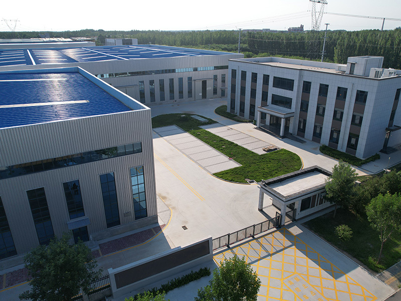
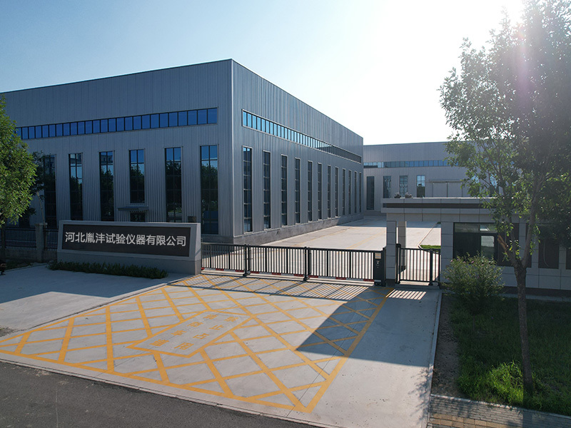
Hebei Yinfeng Experimental Instrument Co., Ltd. is a high-tech enterprise dedicated to the research and development, production, and sales of experimental instruments. The company is headquartered in Hebei Province, relying on the strong industrial foundation and technological innovation resources in the Beijing Tianjin Hebei region. It is committed to providing high-precision and high reliability testing equipment and solutions for material testing, engineering quality control, scientific research experiments and other fields.


Customized Delivery Process
We provide customers with full-process services ranging from pre-sale consultation, customized solution design, equipment installation and commissioning to after-sale technical support.
Online Communication
Provide Custom Drawings
Merchant Quotation
Sign A Contract
Processing And Production
Packaging And Distribution
Confirm Receipt Of Goods
Successful Transaction
Geosynthetic Vertical Permeability Testing Machine
If you need customized products, Contact US !
Share to


Category
Tag list
Request a Quote
We will contact you within one working day. Please pay attention to your email.
Related Products
Content update in progress
Message
We will contact you within one business day. Please note your email address.
Fast navigation
Contact Us
Whatsapp/Tel: +86-15931715356,+86 16631790555
E-mail: qcj@cnhblabequipment.com
Add: Chengnan Industrial Zone, Xian County, Cangzhou City, Hebei Province

Online Message