


- Product Describe
-
Overview
The pavement smoothness meter adopts advanced ARM microcomputer processing and large-scale integrated circuit technology, improving the integration of the entire machine, reducing many unnecessary connectors in the original instrument, thereby increasing the reliability of the system operation and making the overall system performance more stable. The instrument contains a real-time clock that can display time and date and automatically record them. The display uses an LCD method, which reduces power consumption and makes the display clearer. The displacement sensor uses a high-precision displacement sensor with higher accuracy, better stability, and faster testing speed. The power supply uses a 6V7.2AH gel maintenance-free battery, replacing the traditional lead-acid battery. Mechanically, while ensuring test accuracy, precision, and frame rigidity, the instrument's weight is minimized as much as possible, making transportation and handling more convenient and flexible. Therefore, compared with the current 3-meter straightedge measurement and other similar measuring instruments, this instrument not only has advantages such as high measurement accuracy, fast speed, reliable data, and scientific evaluation but also is simple to operate, reliable in work, greatly reduces labor intensity, and improves work efficiency and economic benefits. It is suitable for construction inspection, completion acceptance, and maintenance of highways, urban roads, squares, airport runways, etc., and can also provide reliable pavement analysis data for teaching, design, and research units. This instrument is listed as a standard measuring instrument in the national standard "Asphalt Pavement Construction and Acceptance Specification" (GBJ02-86) and the Ministry of Transport's "Maintenance Technical Specification" (JTJ073-85).
Main Technical Performance
(1) Detection Functions and Accuracy
1. Can automatically measure, calculate, and print the root mean square deviation σ. Sampling intervals of 0.05m and 0.1m are available, with sampling error <0.04mm. Under the same conditions, repeated tests have a statistical deviation of less than 0.2 mm.
2. Data can be manually input; the instrument can automatically print the test date (year, month, day) and the measured road section number (road number, mileage number, stake number, lane number, tolerance setting, sampling interval). Each print increments or decrements the summary number automatically.
3. Automatically calculates and prints the one-way cumulative value H (unit: mm) of the measured road section.
4. Automatically calculates and prints the graphical area value S between the cross-sectional curve and the reference line of the measured road section (unit: cm 2 ).
5. Automatically detects, calculates, and prints the length value L of the measured road section (unit: m), with an error less than 1%.
6. Automatically measures, calculates, and prints the positive and negative tolerance counts (K+, K-). The tolerance standard can be selected according to pavement grade requirements, limited within the range of 1-15 (mm).
7. Can automatically measure, calculate, and print the test speed value v (unit: km/h).
(2) Traction Method and Detection Speed
Can be manually or motor vehicle towed, minimum turning radius 5 m, detection speed should be 6-8 km/h, maximum speed not exceeding 12 km/h. In non-detection conditions (frame shortened, measuring wheel lifted), towing speed is 25 km/h.
(3) Working Environment Temperature : -10℃ to +60℃
(4) Power Supply and Power Consumption : Gel maintenance-free battery, 12V7.2AH.
Structural Principle
The smoothness meter consists of mechanical and electrical parts. The electrical part is separately installed in the instrument box, connected by a cable to the interfaces of the displacement sensor and distance sensor, allowing for easy disassembly.
(1) Mechanical Structure (see figure below)
The mechanical part consists of the following components;
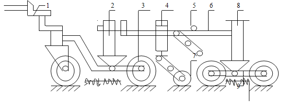
1. Traction part: composed of a connecting plug and a pull rod, connected to the front axle by a nut.
2. Front axle
3. Wheels: composed of eight motorcycle wheels with pneumatic tires arranged on front and rear frames.
4. Displacement sensor: frequency modulation inductive displacement measurement system.
5. Locking mechanism
6. Main frame: including telescopic square tubes, guiding structure, rear frame, etc.
7. Measuring wheel: composed of a compression spring and lifting mechanism, rubber wheel, and distance sensor.
8. Rear axle
9. Wheel frame
(2) Electrical Structure
This instrument uses an advanced 32-bit ARM chip and high-precision AD chip and displacement sensor, making the system's acquisition accuracy higher and speed faster, resulting in more stable data. The system uses a 2G SD card for storage, allowing unlimited saving.
1. Display module is a 128*64 LCD, which has lower power consumption and longer standby time.
2. Button functions:
"Menu" key: set instrument parameters and view data information.
"Back/Reset" key: exit system parameters and reset displacement sensor.
"Confirm/Print" key: confirm set data and print data information.
"Up" key: increment data by one.
"Down" key: decrement data by one.
"Left" key: move parameter setting to the left.
"Right" key: move parameter setting to the right.
"Start" key: start and end the experiment.
"Query" key: query data stored on the memory card.
"Power On" key: turn on the system power.
"Power Off" key: turn off the system power.
- Printer: This printer is a thermal printer.
- 12V1A: This port is the charging port.
- Sensor: This port connects to the 6-core cable of the sensor on the eight-wheel instrument.
- USB: Connects to the computer for data reading.
- Power: This is the main switch of the system. It is recommended to switch it off when the instrument is not in use.
- Operating Instructions
- Preparation for Test Vehicle Use
- The instrument test vehicle has two states: storage/transport state and measurement/testing state. During transport, remove the fixing bolts, retract the front telescopic square tube and rear frame inward, then fix with bolts, suspend the measuring wheels, and disconnect all plugs. In the testing state, remove the fixing bolts, extend the frame into position, fix with bolts, and lower the measuring wheels to make them closely contact the ground.
- Install the printing paper, paying attention to the front and back sides of the paper.
- Connect all cables properly, paying attention to the direction when connecting cables.
- Usage Steps
Turn on the power and press the "Power On" button; the controller will display the monitoring page.
1. Test Parameter Setting
Main Page
① "Test Parameter Setting"
Press the "Confirm" button
"① Road Number Setting"
"② Mileage Number Setting"
"③ Starting Stake Number Setting"
"④ Road Section Number Setting"
"⑤ Limit Difference Setting"
"⑥ Sampling Interval Setting"
"⑦ Increment or Decrement Setting"
Press the "Menu" button
2. Sensor Calibration
Press the "Menu" button
② "Sensor Calibration"
Press the "Menu" button
Enter password "000000"
Enter "111111"
First calibration point, follow the prompts to operate
Press the "Confirm" button
Second calibration point, follow the prompts to operate
Press the "Confirm" button
End sensor calibration
Main Page
Main Page
3. System Backlight Setting
Set values according to prompts
"③ System Backlight Setting"
End
Press the "Confirm" button
Press the "Confirm" button
Press the "Menu" button
Main Page
4. Date and Time Setting
Set values according to prompts
"④ Date and Time Setting"
End
Press the "Confirm" button
Main Page
Press the "Menu" button
Press the "Confirm" button
- System Parameter Setting
Non-technical personnel should not operate this parameter, as it will affect the normal use of the instrument.
(3) Usage Precautions
- During transport, steering, parking, and other non-measurement states, the measuring wheels must be suspended to avoid unnecessary wear and collision.
- Test speed must be kept within 10 km/h. If the road condition is poor, reduce the speed accordingly to avoid excessive frame vibration affecting measurement accuracy. For long-distance transport, the testing instrument should be placed inside the transport vehicle. For short-distance transport, it can be towed directly by a motor vehicle, but the speed should be less than 25 km/h to avoid damage caused by excessive speed and vibration.
- The controller is debugged before delivery. Users must not open the controller panel or arbitrarily replace components or solder wires to avoid damaging the instrument. Otherwise, our factory will not provide repairs. If there is a circuit fault, please contact our factory.
Maintenance and Care
- The instrument uses an internal rechargeable battery, which can be used continuously for more than 20 hours when fully charged (turning off the backlight can extend usage time).
- Before each use, fully charge the battery (generally about ten hours of charging).
- If the instrument is not used for a long time, charge it once every 2-3 months to ensure the battery is not damaged.
- The flatness meter is a precision electronic instrument, including sensors, meters, printers, and other components. Do not expose it to rain or moisture. When not in use, store it properly and power it on regularly to avoid damage.
- Bearings and moving parts on the frame should be lubricated regularly to prevent rust and wear. Check whether the connecting bolts are tightened before and after use. Pay special attention to checking after long-distance transport.
- Wear on the measuring wheels affects measurement accuracy. After sufficient mileage, check the diameter and replace it in time. The standard diameter of the measuring wheel is Ф127.40mm.
- The instrument's cable is prone to disconnection due to improper use. Use a multimeter to check the continuity of the wiring. The wiring diagram of the cable connection is attached. When troubleshooting, broken wires must be soldered firmly, and wires must not touch each other to avoid affecting the instrument's use.
Before and after use, the displacement sensor measuring rod must be wiped clean.
Packing List
1. Main unit: 1 set;
2. Displacement sensor: 1 set;
3. Manual: 1 copy;
4. Certificate of conformity: 1 copy;
5. Counting sensor: 1 piece;
6. Charger: 1 piece;
7. Computer communication data cable: 1 piece;
8. Sensor cable (5 meters): 1 piece;
9. Memory card: 1 piece;
Company Profile
Hebei Yinfeng Experimental Instrument Co., Ltd. is a high-tech enterprise dedicated to the research and development, production, and sales of experimental instruments. The company is headquartered in Hebei Province, relying on the strong industrial foundation and technological innovation resources in the Beijing Tianjin Hebei region. It is committed to providing high-precision and high reliability testing equipment and solutions for material testing, engineering quality control, scientific research experiments and other fields.


Customized Delivery Process
We provide customers with full-process services ranging from pre-sale consultation, customized solution design, equipment installation and commissioning to after-sale technical support.
Online Communication
Provide Custom Drawings
Merchant Quotation
Sign A Contract
Processing And Production
Packaging And Distribution
Confirm Receipt Of Goods
Successful Transaction
Previous:
Next:
Continuous Flatness Meter
If you need customized products, Contact US !
Share to


Tag list
Request a Quote
We will contact you within one working day. Please pay attention to your email.
Related Products
Content update in progress
Message
We will contact you within one business day. Please note your email address.
Fast navigation
Contact Us
Whatsapp/Tel: +86-15931715356,+86 16631790555
E-mail: qcj@cnhblabequipment.com
Add: Chengnan Industrial Zone, Xian County, Cangzhou City, Hebei Province

Online Message