


- Product Describe
-
I. Overview
The TCDR-300 thermal conductivity meter is a new type of dual-plate testing device designed in accordance with GB10294-2008, "Determination of Steady-State Thermal Resistance and Related Properties of Thermal Insulation Materials—Guarded Hot-Plate Method." It is used to measure the thermal conductivity of various homogeneous slab-shaped thermal insulation materials as well as non-conductive thermal materials. The meter features an automatic microcomputer control system with a high degree of intelligence, making it an ideal choice for conducting such testing projects in China today.
II. Testing Items:
Used to measure the thermal conductivity of various homogeneous slab-shaped thermal insulation materials and non-conductive thermal materials.
III. Principle:
Under steady-state conditions, within the central measurement zone of the guarded hot plate apparatus, and in a uniform, plate-like specimen with parallel surfaces, a one-dimensional, steady-state heat flux is established, analogous to that found in an infinite flat plate bounded by two parallel, uniformly heated plates.
IV. Standards:
GB10294-2008 ≤Determination of Steady-State Thermal Resistance and Related Properties of Thermal Insulation Materials—Guarded Hot Plate Method≥
V. Technical Parameters:
1. Model: TCDR-300
2. External dimensions: 1030*800*1500
3. Specimen specifications: Measured at 150*150 mm; protection at 300*300 mm.
4. Specimen thickness: ≤60mm
5. Thermal conductivity measurement range: 0.01–2 W/(m·K)
6. Cold plate temperature: 5℃ - 90℃
7. Hot plate temperature: ≤120℃
8. Test accuracy: ≤3%
9. Test repeatability: ≤1%
10. Power supply: 3 kW, 220 V
VI. Test Device Structure:
It adopts the double-specimen shielding plate method (GB10294-2008) and consists of a microcomputer-based automatic control system, a metering heating unit, a cold plate unit, a shielding unit, an external shielding unit, a measurement system, a clamping system, and a refrigeration mechanism.
1. Microcomputer Automatic Control System:
The computer’s output signals, after being processed by I/O and D/A conversion, control the corresponding actuators to achieve functions such as temperature control, computation, temperature data acquisition, printing of test reports, and display of process curves. The human-machine interface window displays temperature values for each surface and features a self-diagnosis function.
2. Measuring and Heating Unit:
Aluminum plates are used as heating panels because of their high thermal conductivity, which ensures a more uniform temperature distribution across the heating surface and reduces thermal inertia, thereby improving the accuracy of measurement results.
3. Cold plate unit:
A constant-temperature water tank is used to control the temperatures of the two cold plates. The temperature of the cold plates can be set, and a microcomputer provides automatic control, which helps ensure that the temperature difference between the two sides tends to be uniform.
4. Protective Unit:
Using the same panel material as the metering heating unit, precisely control the temperature difference across the gap to reduce testing errors.
5. External protection unit:
The protective cover made of cork serves as an external protective unit, stabilizing the experimental environmental conditions and thereby enhancing test accuracy.
6. Measurement system:
By using the highly stable American Dallas 18B20 digital temperature sensor and a high-precision DC power sensor, we ensure more accurate data acquisition results.
7. Clamping System:
Using pneumatic technology, the cylinder automatically clamps the specimen, eliminating the need for manual adjustment of clamping force and making specimen installation extremely convenient.
8. Refrigeration mechanism:
It can achieve rapid cooling of the cold plate and measure the average temperature of the specimen below room temperature, thereby expanding the detection range and making it independent of ambient temperature.
7. Operating Instructions:
1. Manual operation
Connect the power supply and press the “Coefficient Start” button on the control cabinet. The indicator light will turn green. By briefly pressing either the “Cold Plate Loose” or “Cold Plate Tight” button, you can open or close the specimen clamping device, allowing experimental personnel to install and remove specimens.
2. Microcomputer operating system:
1. Connect the microcomputer system, turn on the power, start the computer and enter the operating system. Double-click the thermal conductivity icon to enter the main interface.
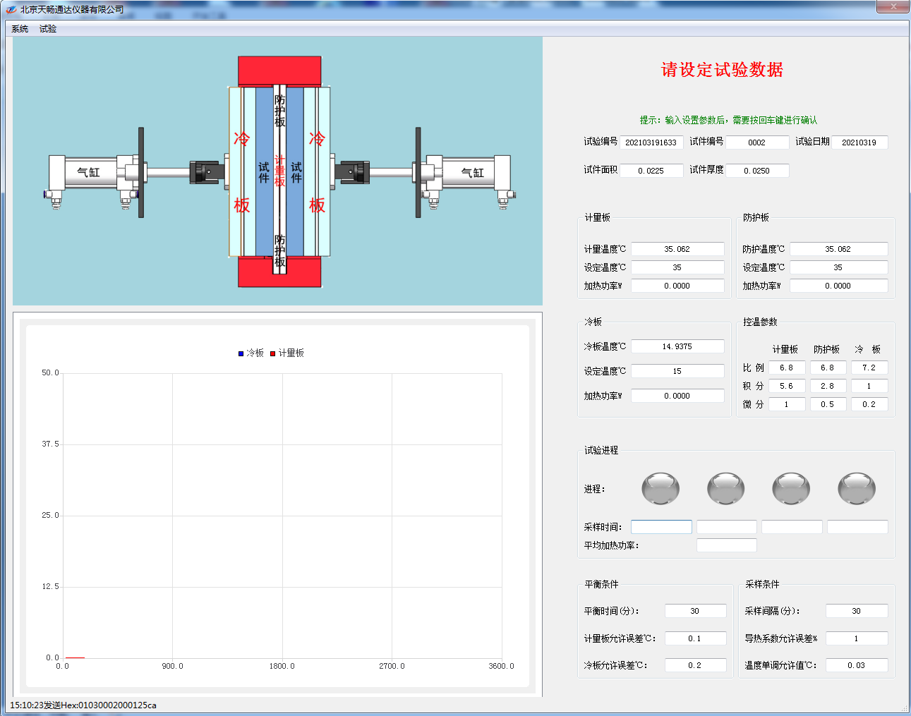
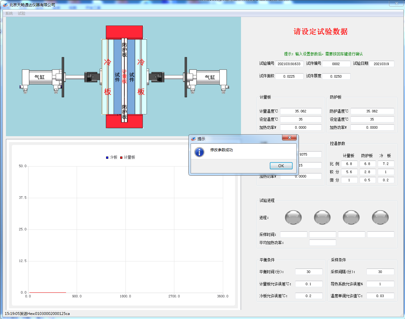
- Set the relevant parameters according to the actual test conditions, including the test number, specimen number, test date, specimen area, specimen thickness, set temperature of the measuring plate, set temperature of the protective plate, and set temperature of the cooling plate. Please note that after entering the setting data, you need to press the Enter key to confirm it. A prompt window will appear once the settings are successfully configured.
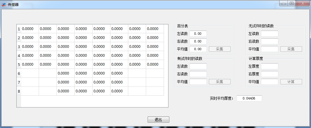
- Click “Sensor” under the “System” menu to monitor whether the sensor is functioning properly.
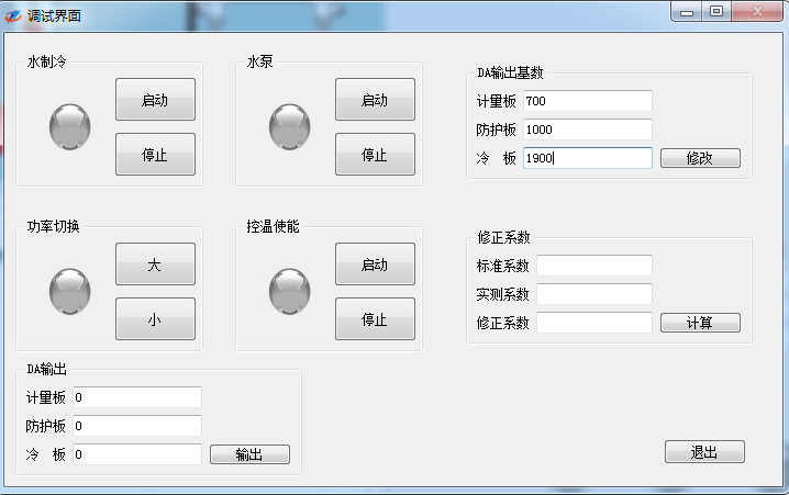
- Click “Debug” under the “System” menu to open the debugging interface.
5. Click “Start” under the “Experiment” menu to enter the experiment state.
6. If the cold plate’s set temperature is ≥ (ambient temperature + 10)℃, you must press the “Stop” button for water-based cooling. In principle, all other settings remain unchanged from those originally configured at the factory; any deviations shall be subject to on-site adjustments made by service personnel.
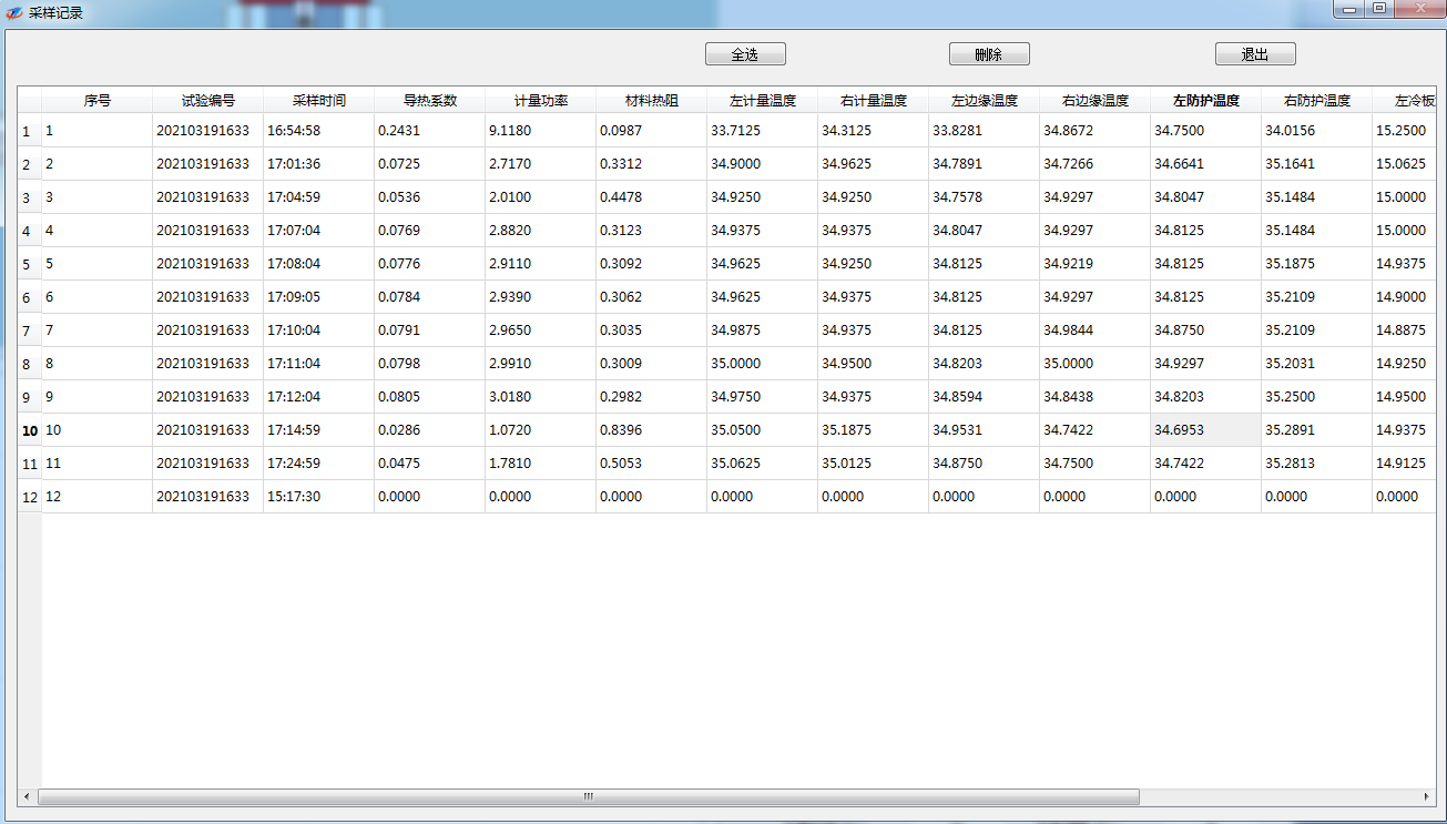
7. Click “Sampling Records” under the “Experiment” menu on the main screen to enter the test records screen. On the test records screen, you can view all experimental data collected throughout the entire experiment and also delete historical data.
8. Click “Test Records” under the “Test” menu on the main screen to access the test records screen. This is the original record of the most recent experiment.
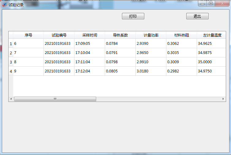
Click “Print” in the test log to generate a printout:
9. The experiment will end automatically. If you wish to stop the experiment during its course, click “End” under the “Experiment” menu on the main screen to exit the experimental state.
10. Click “Exit” under the “System” menu on the main screen to exit the main screen.
11. After removing the specimen, disconnect the power supply to end the experiment.
12. Organize the lab report.
8. Precautions:
1. After the experiment, special attention should be paid to cleaning and rust-proof maintenance.
2. After the equipment is installed and debugged, the operator should regularly check whether the grounding protection of the control box is functioning properly.
3. The environment and equipment should be kept generally clean, with the ambient temperature maintained between 18-25℃ and relative humidity below 50%.
4. The antifreeze or water in the radiator should be kept clean, and the antifreeze or water should be changed regularly.
5. Regularly calibrate the power sensor.
6. When the entire machine is left unused for an extended period, unplug the main power cord and take care to prevent rust and dust accumulation.
Any changes will be subject to the training provided to service personnel; no further notice will be given.
Company Profile
Hebei Yinfeng Experimental Instrument Co., Ltd. is a high-tech enterprise dedicated to the research and development, production, and sales of experimental instruments. The company is headquartered in Hebei Province, relying on the strong industrial foundation and technological innovation resources in the Beijing Tianjin Hebei region. It is committed to providing high-precision and high reliability testing equipment and solutions for material testing, engineering quality control, scientific research experiments and other fields.


Customized Delivery Process
We provide customers with full-process services ranging from pre-sale consultation, customized solution design, equipment installation and commissioning to after-sale technical support.
Online Communication
Provide Custom Drawings
Merchant Quotation
Sign A Contract
Processing And Production
Packaging And Distribution
Confirm Receipt Of Goods
Successful Transaction
Previous:
TCDR-300 Thermal Conductivity Meter
If you need customized products, Contact US !
Share to


Category
Tag list
Request a Quote
We will contact you within one working day. Please pay attention to your email.
Related Products
Content update in progress
Message
We will contact you within one business day. Please note your email address.
Fast navigation
Contact Us
Whatsapp/Tel: +86-15931715356,+86 16631790555
E-mail: qcj@cnhblabequipment.com
Add: Chengnan Industrial Zone, Xian County, Cangzhou City, Hebei Province

Online Message