



- Product Describe
-
I. Applicable Standards
The SYD-3536(A) Asphalt Flash and Fire Point Tester is designed and manufactured in accordance with the national standard GB/T 3536-2000 "Test Methods for Flash and Fire Points of Petroleum Products" (Cleveland Open Cup Method), which specifies the determination of flash and fire points for petroleum and petroleum products.
This instrument is also suitable for the JTG E20—2011 Highway Specification T0611—2011 "Bitumen Flash and Fire Point Test (Cleveland Open Cup Method)" and the international standard ISTMD 2000 test.
II. Uses and Scope of Application
This instrument is suitable for determining the flash point and fire point of viscous petroleum asphalt, coal tar asphalt, and liquid petroleum asphalt materials with a flash point above 79°C using the Cleveland Open Cup (referred to as COC), aiding in the assessment of construction safety.
III. Operating Conditions of the Instrument
Power supply: AC220V ±10% / 50Hz
Ambient temperature: -10°C to 50°C
Relative humidity: ≤85%
Maximum power: 800W
IV. Main Features and Technical Parameters
SYD-3536 Model:
1. Automatic sweeping and ignition;
2. Electric furnace heating power is continuously adjustable from 0 to 800W;
3. The heating wire is protected by a transparent quartz tube, features no open flame, is explosion-proof, and heats up rapidly;
SYD-3536A Model:
1. Automatic sweeping and ignition;
2. Electric furnace heating power is continuously adjustable from 0 to 800W (with digital PWM control);
3. The heating wire is protected by a transparent quartz tube, features no open flame, is explosion-proof, and heats up rapidly;
4. Chinese graphical LCD display with digital temperature readout (utilizing a low thermal resistance PT100 temperature sensor).
5. Equipped with an advanced digital temperature control algorithm, it can automatically and rapidly adjust the heating rate.
6. The flash point and ignition temperature can be automatically recorded by pressing a button.
V. Main Structure and Principle Block Diagram
1. The structure is shown in the figure.

Figure 1 SYD-3536

Figure 2 SYD-3536A
2. Operating Procedures

The figure shows a schematic diagram of the SYD-3536A panel.
Heating: Used to turn the heating function on or off.
Ignition: Used to turn the scanner on or off.
Flash Point Record / Ignition Point Record: Press the button when the corresponding phenomenon is observed, and record the corresponding temperature value.
Settings/Direction Keys: Used to open the settings interface and modify parameters, including control parameters for adjusting the heating rate, among other things.
Heating adjustment knob: Provides coarse control over the heating rate.
6. Installation and Usage Steps
1. Open the packaging box, inspect the instrument’s exterior and associated accessories. If there is no damage or missing parts, proceed with installation according to the structural diagram.
2. Check whether the power grounding is properly connected.
3. Turn on the power switch—the indicator light will illuminate, and you can then proceed with the experimental operation.
4. Wash the sample cup with solvent, dry it thoroughly, and then mount it on the stand.
5. Install the thermometer by inserting it vertically into the sample cup, ensuring the mercury bulb (temperature sensor) is approximately 6.5 mm above the bottom of the cup and positioned 16 mm from the cup’s edge on the side opposite the igniter.
6. After preparing the sample, carefully pour it into the sample cup up to the marked line, ensuring that no asphalt adheres to other parts of the cup. (Note: The sample must not be heated above 55°C below its flash point.)
7. All equipment should be placed in a dimly lit indoor area with no significant air circulation, and surrounded on three sides by wind shields.
8. Connect the igniter to a full-pressure container of flammable gas (such as liquefied propane or natural gas) using a flexible hose. Turn the igniter to one side, ignite the gas, and adjust the flame until it forms either a standard spherical shape or a small spherical test flame with a diameter of 4 mm ± 0.8 mm.
7. General Test Procedures
1. Begin the heating test, rapidly increasing the temperature at a rate of 14°C/min to 17°C/min. Once the sample temperature reaches 56°C below the expected flash point, adjust the heater to slow down the heating rate, ensuring that by the time the temperature is 28°C below the expected flash point, the heating rate is precisely controlled within 5.5°C/min ± 0.5°C/min.
2. Begin when the sample temperature reaches 28°C below the expected flash point, and press the igniter button every 2°C interval. Each time, use the igniter to sweep the test flame horizontally in an arc with a 150-mm radius, centered along the rim of the test cup—traversing from one side of the cup rim to the other in approximately 1 second. At this moment, ensure that the igniter produces a flame sphere measuring 4 mm ± 0.8 mm in diameter, positioned precisely 2.5 mm above the rim of the test cup. (Note: Do not breathe toward the sample cup during the test.)
3. When a brief, instantly extinguishing blue flame first appears on the surface of the sample liquid, immediately read and record the temperature displayed on the thermometer (or screen) as the sample’s flash point. Be careful not to mistake the bluish-white flame surrounding the test flame for the actual flash point flame. Then, press the “Flash Point Record” button, and the instrument will automatically log the current temperature (SYD-3536A).
4. Continue heating, maintaining a sample heating rate of 5.5°C/min ± 0.5°C/min, and perform the ignition test using the igniter as described above.
5. When the sample ignites immediately upon contact with the flame and continues to burn for at least 5 seconds, stop heating and record the temperature shown on the thermometer as the sample’s flash point. Then, press the “Flash Point Record” button, and the instrument will automatically log the current temperature (SYD-3536A).
6. For the same sample, conduct at least two parallel tests. If the difference between the two measurement results does not exceed the allowable limit of 8°C for repeatability testing, take the integer part of their average as the final test result.
7. Precision or Permissible Difference
The allowable differences for the repeatability test are: flash point, 8°C; ignition point, 8°C.
The allowable difference for reproducibility tests is: flash point ±16°C, and ignition point ±14°C.
8. After the experiment, ensure thorough cleaning and turn off the power supply.
Company Profile
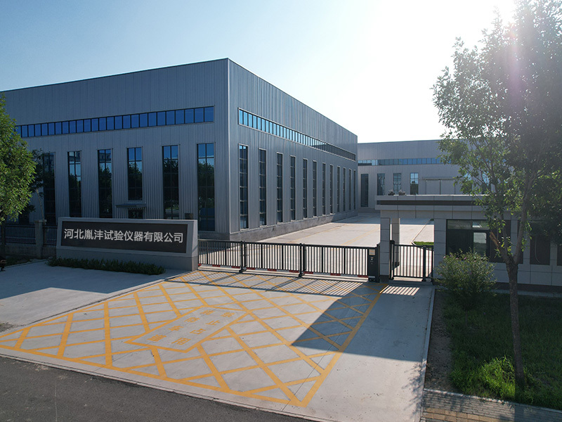
Hebei Yinfeng Experimental Instrument Co., Ltd. is a high-tech enterprise dedicated to the research and development, production, and sales of experimental instruments. The company is headquartered in Hebei Province, relying on the strong industrial foundation and technological innovation resources in the Beijing Tianjin Hebei region. It is committed to providing high-precision and high reliability testing equipment and solutions for material testing, engineering quality control, scientific research experiments and other fields.



Customized Delivery Process
We provide customers with full-process services ranging from pre-sale consultation, customized solution design, equipment installation and commissioning to after-sale technical support.
Online Communication
Provide Custom Drawings
Merchant Quotation
Sign A Contract
Processing And Production
Packaging And Distribution
Confirm Receipt Of Goods
Successful Transaction
Previous:
Next:
Cleveland Asphalt Flash and Fire Point Tester
If you need customized products, Contact US !
Share to


Category
Tag list
Request a Quote
We will contact you within one working day. Please pay attention to your email.
Related Products
Content update in progress
Message
We will contact you within one business day. Please note your email address.
Fast navigation
Contact Us
Whatsapp/Tel: +86-15931715356,+86 16631790555
E-mail: qcj@cnhblabequipment.com
Add: Chengnan Industrial Zone, Xian County, Cangzhou City, Hebei Province

Online Message