



- Product Describe
-
Overview
The DZ-08 vibratory compaction and molding machine is a specialized piece of equipment designed and manufactured in accordance with the requirements of T084-2009 in the “Test Procedures for Inorganic-Bound Stabilized Materials in Highway Engineering (JTG 3441-2024)” to provide the technical accessories necessary for producing test specimens of semi-rigid base materials by the vibration method. It is used to fabricate various types of test specimens for inorganic-bonded stabilized granular materials, including cylindrical specimens for testing unconfined compressive strength, indirect tensile strength, and compressive resilient modulus, as well as beam-type specimens for determining the coefficient of thermal shrinkage, the coefficient of drying shrinkage, flexural strength, and flexural resilient modulus. This equipment complies with the new standard JTG 3441-2024, “Test Procedures for Inorganic-Bound Stabilized Materials in Highway Engineering.”
Main Technical Specifications
1 Static pressure 1900 N (adjustable) 2 Excitation force 6,800–6,900 N (adjustable) 3 Vibration frequency 28–30 Hz (adjustable) 4 Vibration time 90–120 s (higher dry density); 70–90 s (molded specimen) 5 Test specimen mold Cylindrical Specimen Mold 6 Steel mold Inner diameter 152 mm, height 170 mm, wall thickness 10 mm; inner diameter 150 mm, height 230 mm, wall thickness 10 mm. 7 Steel mold retaining ring Inner diameter: 152 mm; height: 50 mm; wall thickness: 10 mm 8 External dimensions (length × width × height) 1760×760×1750 mm 9 Overall weight 900 kg 10 Power supply AC 380 V (three-phase four-wire system with a working neutral) Equipment Installation
1. Foundation
During the mold-making process, this equipment exerts substantial impact forces on the floor. Therefore, the equipment foundation must have an anti-vibration capacity of at least 10,000 N. A 5-mm-thick hard rubber pad should be placed beneath the equipment base, and the base should then be securely fastened with anchor bolts.
There shall be a clearance of at least 1 meter around the equipment to facilitate operation and maintenance.
2. Power Supply: The equipment requires a three-phase, four-wire 380 V, 4 kW power supply, and must be reliably grounded.
3. Equipment Connection
The variable-frequency drive and control instrument are mounted on a horizontal floor. There are a total of four aviation connectors with different pin configurations connecting the electrical control cabinet to the variable-frequency drive and the equipment itself, allowing for one-to-one correspondence and connection.
Operation and Usage
1. Operation of the Variable Frequency Drive (Note: The VFD is factory-set to standard test values; do not adjust these settings without authorization.)
When the power switch on the control box panel is turned on, the inverter is powered up, and both the digital display window and the LCD screen will show information. Upon startup, the frequency displayed on the inverter is the previously set value; if no change is required, simply press the “FWD” key to confirm the preset frequency.
Note: The operating frequency required for this equipment is 28–30 Hz. If the set frequency is too low, the resulting excitation force will be insufficient. Conversely, if the set frequency is too high, the excitation force will increase substantially, potentially damaging the equipment. Therefore, when starting mold-making operations, it is essential to verify that the inverter’s output frequency is maintained within the 28–30 Hz range.
2. The “Raise” button controls the lifting of the guiding mechanism and the indenter, providing sufficient space for the test.
3. The “Lower” button controls the guiding mechanism and lowers the pressure head onto the test mold.
4. “Start” Button: After the time setting is completed, press the “Start” button to activate the excitation mechanism, which will then commence operation and carry out the test according to the set parameters.
5. “Emergency Stop” Button: In the event of an accident during the test, or if adjustments or other unforeseen circumstances arise, the emergency stop button may be pressed to immediately halt the operation of the excitation mechanism. Note that the emergency stop button is self-locking; after it has been pressed, it must be pressed again to reset the button once the inspection is complete and work is to resume. During this process, the time-control instrument will continue to operate without interruption; work will only resume after the preset duration has elapsed, or the timing must be reset.
6. Precautions for the Buttons: The up and down buttons are momentary-control switches. During operation, closely monitor the position of the guide rod to prevent damage to the guide bushing.
Note: The lifting and lowering motor for load application and removal is powered by a three-phase supply. Since the phase sequence of the motor wiring at the factory may not match the phase sequence of the user’s three-phase power supply, the control box buttons for loading and unloading may operate in the opposite direction to the movement of the load head. In this case, with the power off, open the motor junction box and swap any two of the three power supply wires at the terminal block. This will ensure that the button actions correspond to the motor movements.
7. Vibration
Once it is confirmed that the inverter frequency is within the range of 28–30 Hz and that the punch is properly aligned with the die, the vibration button can be activated to compact and form the sample. When the vibration compaction reaches the preset stroke, pressing the stop button will immediately halt the vibration compaction process.
8. Vibration and Pressing Time
As soon as vibratory compaction is initiated, the timer starts; when vibratory compaction ceases, the timer stops and displays the duration of the compaction process.
Mold making
1. Material Preparation and Specimen Fabrication
For the preparation of test specimens and their fabrication, please refer to the “Notes and Relevant Instructions for the Vibration Compaction Test Method for Inorganic-Bonded Stabilized Materials” specified in T 0842—2009 of the “Test Procedures for Inorganic-Bonded Stabilized Materials in Highway Engineering” (JTG E51-2009).
2. Mold for
Place the mold containing the test specimen on the equipment base plate, adjust its position so that the indenter can descend precisely into the mold cavity, and then secure the mold to the base plate using screws.
3. Mold Making
After the indenter and die have been aligned and securely clamped, press the loading button to lower the platen on the lead screw by approximately 100 mm. At this point, the entire applied load is transmitted through the indenter and fully borne by the test specimen in the die, thereby completing the preparatory steps.
When initiating the compaction vibration, record the initial position on the right-hand scale of the frame. Then start the compaction vibration again. Once the predetermined compaction position is reached, press the stop button to complete the forming operation.
Caution: The entire lifting and lowering range of the load is 150 mm. A scale is mounted on the right side of the frame; the load and indenter may only be moved within this range—do not exceed it. Failure to comply may damage the lead screw and limit slots.
Sample Preparation
1. Install the appropriate indenter according to the required shape of the test specimen; for cylindrical specimens, the dimensions are 150 mm in diameter and 150 mm in height.
2. Spread one portion of the test sample evenly in a metal pan, and spray water uniformly over the sample according to the amount calculated based on the optimum moisture content determined in advance through the standard compaction test. Then, use a small shovel to thoroughly mix the sample until it is uniformly blended.
In the formula: Qw — the amount of water to be added to the test sample (g)
Qn—Mass of aggregate in the mixture (g) and its original moisture content Wn, i.e., air-dry moisture content (%).
Qc—Mass of cement or lime in the mixture (g), with an initial moisture content of Wc (%).
W—The required moisture content of the mixture (%).
3. Add the required binding materials, such as cement and lime-fly ash, to the saturated test specimens and thoroughly mix them to a uniform state using a small shovel, trowel, or other suitable tools. For test specimens containing cement, the subsequent compaction test must be completed within 1 hour after mixing; any specimens mixed more than 1 hour ago shall be discarded (except for those stabilized with lime or lime–fly ash).
4. Divide the thoroughly mixed material into four equal portions using the quartering method, and sequentially pour each portion into the mold while simultaneously tamping it with a wooden rod approximately 2 cm in diameter. After the entire batch has been placed in the mold, level the surface and apply slight compaction, then cover it with a pre-cut piece of plastic sheeting. Place the test mold together with the compacted mixture on the steel base plate of the vibration compaction machine, and secure the mold base plate to the machine’s base plate using a pressure plate.
5. Align the vibration ram with the test mold, then lower the guide frame to ensure tight contact between the vibration ram and the mixture inside the steel mold. Inspect the bolts and other connection points on the vibratory compaction machine and verify that no objects are placed on the machine body.
6. Set the vibration time, then turn on the vibration switch to start vibration compaction, and carefully observe whether the vibration state has reached the bouncing state.
7. Raise the vibrating compaction head. Loosen the bolts securing the mold platen, then remove the test mold together with the compacted mixture. Next, take off the mold collar; at this point, the top surface of the vibration-compacted mixture should be flush with the upper edge of the steel mold.
8. Support the bottom of the mold with shims, then carefully place the mold together with the compacted mixture in the designated location. After allowing the mixture to stand for a specified period according to its type, use a demolding device to extrude the compacted mixture from the mold. For beam-shaped test specimens, first loosen the bolts and then carefully remove the side plates; however, the specimen must remain on the steel base plate and should not be moved until the mixture has developed sufficient early strength.
9. Once the test specimen has been demolded or can be moved, it shall be immediately wrapped with a plastic film and placed in a curing room for curing; the curing conditions shall be the same as those specified in the code for the static compression method.
10. For detailed procedures on the preparation of the above test specimens, refer to the vibration compaction method for shaping semi-rigid base course materials as specified in the JTG D50—2006 Highway Pavement Design Code issued by the Ministry of Transport. Also refer to the precautions and relevant instructions for the tests.
Precautions
1. The equipment must be installed on a foundation capable of withstanding excitation forces exceeding 10,000 N and secured with anchor bolts.
2. The equipment must be reliably grounded using a dedicated grounding conductor; the neutral line must not be used as a substitute. This equipment must be protected against phase-loss operation, as such conditions can result in equipment damage.
3. The frequency setting range for the variable-frequency drive is 28–30 Hz, and this must be confirmed before starting the vibratory compaction operation.
4. The load’s travel range is 150 mm, and it must not exceed the limits of the limit slots.
5. During vibration compaction, operators must not touch the equipment’s mechanical components to prevent injury.
6. The electric lifting mechanism is equipped with a backup manual handwheel at the worm gear and worm assembly at the upper end of the frame, to be used in the event of an electric motor failure. Under normal circumstances, the handwheel should be removed from the rotating mechanism to prevent it from being flung off during high-speed rotation and causing injury.
7. During electric lifting, pay close attention to the lifting height and stop when appropriate; never lift too high, as this could cause the lifting rod to snap.
8. During electric descent, an appropriate margin for compaction should be left; generally, the plunger should be lowered by more than 5 cm after it has been pressed against the test specimen.
9. Vibration Time: In experimental trials, the vibration-pressing time is critical, typically ranging from 90 to 120 seconds. Either too long or too short a duration can result in insufficient compaction.
10. The compacted density achieved through vibratory compaction should be slightly higher than that of semi-rigid base materials. The technical specifications for the vibratory compactor are generally applicable; however, appropriate adjustments may be necessary based on different mix designs and site conditions, such as vibration frequency and static compaction pressure.
11. Regarding the correlation of semi-rigid base materials, numerous testing agencies across the country have conducted extensive comparative tests; however, no definitive correlation with the Marshall compaction method has yet been established.
12. At the factory, the vibration force is pre-set at 6,800 N (at 28 Hz). The equipment is also supplied with two sector-shaped counterweights, which are mounted on the gear. During installation, all mounting screws must be securely tightened; otherwise, safety hazards may arise. When these two counterweights are installed and the upper ends of the continuously adjustable counterweights on the opposite side of the shaft are aligned and leveled (with the upper ends of the two sectors lying in the same plane and the lower ends forming a circular arc), the total vibration force will be approximately 10,000 N (equivalent to 1,000 kg).
On Some Common Problems Encountered in Experiments
Fault phenomenon
Cause of the failure
Solution
1. The instrument does not operate or the inverter does not light up after power is applied. 1. No power on the supply side.
2. Instrument burnout 1. Locate the power supply line
2. Replace the instrument
2. No vibration after startup 1. Inverter parameter error
2. Phase loss in the vibration motor
3. Vibration motor gear jamming 1. Adjust parameters
2. Locate the line
3. Adjust the gear
3. Compaction cannot be raised or lowered: 1. Phase loss in the motor
2. Electric lead screw damage 1. Locate the wiring
2. Replacement or repair of the electric lead screw
4
After vibration, the parts are not compacted properly. 1. Incorrect frequency.
2. The equipment base is not securely fastened.
3. Short vibration time 1. Adjust the frequency
2. Adjust the fixed base
3. Adjust the time
5 Mechanical Maintenance and Servicing 1. Excessive excitation force can cause screws to loosen easily.
2. Excessive dust and component lubrication 1. Regularly tighten screws
2. Regular dust removal and lubricant addition
Random Attachment
Vibration Compaction Molding Machine Main Unit One unit
Control chassis One unit
Cylindrical test mold Three pieces
Anchor bolts Six pieces
One copy of the instruction manual and one copy of the certificate of conformity.
Company Profile
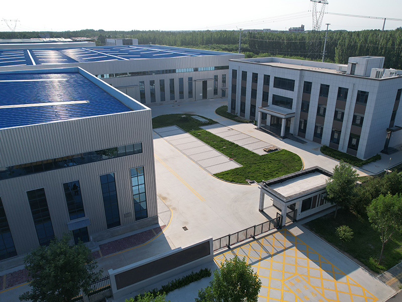
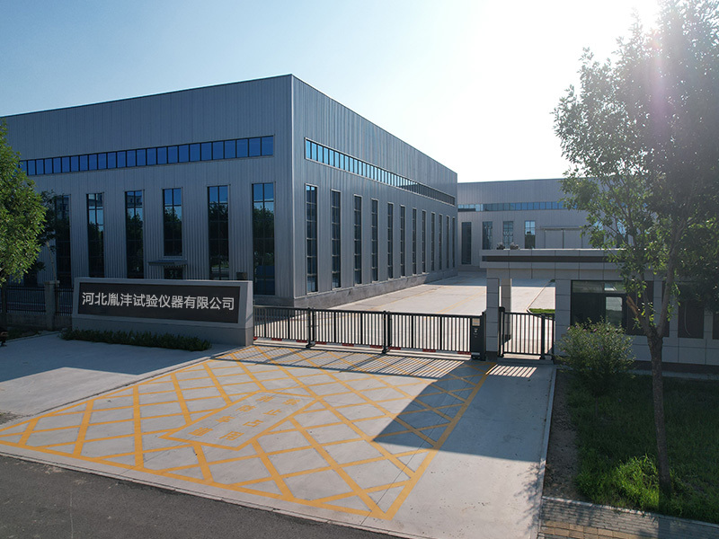
Hebei Yinfeng Experimental Instrument Co., Ltd. is a high-tech enterprise dedicated to the research and development, production, and sales of experimental instruments. The company is headquartered in Hebei Province, relying on the strong industrial foundation and technological innovation resources in the Beijing Tianjin Hebei region. It is committed to providing high-precision and high reliability testing equipment and solutions for material testing, engineering quality control, scientific research experiments and other fields.


Customized Delivery Process
We provide customers with full-process services ranging from pre-sale consultation, customized solution design, equipment installation and commissioning to after-sale technical support.
Online Communication
Provide Custom Drawings
Merchant Quotation
Sign A Contract
Processing And Production
Packaging And Distribution
Confirm Receipt Of Goods
Successful Transaction
Large-scale Inorganic Binder Vibratory Compactor
If you need customized products, Contact US !
Share to


Category
Tag list
Request a Quote
We will contact you within one working day. Please pay attention to your email.
Related Products
Content update in progress
Message
We will contact you within one business day. Please note your email address.
Fast navigation
Contact Us
Whatsapp/Tel: +86-15931715356,+86 16631790555
E-mail: qcj@cnhblabequipment.com
Add: Chengnan Industrial Zone, Xian County, Cangzhou City, Hebei Province

Online Message