



- Product Describe
-
Overview
This instrument is used to determine the permeability of various types of geotextiles. It complies with the requirements for instrumentation specified in GB/T 15789-2005, “Determination of Vertical Permeability Characteristics of Geotextiles and Related Products under Unloaded Conditions.”
Principle
Determine the vertical water flow rate through a single layer of geotextile under specified conditions.
Technical Specifications
Maximum hydraulic head difference 250mm Gripper inner diameter 50±0.5mm Applicable specimen thickness 20mm Time Controller Settable from 0 to 999.9 seconds, with a control accuracy of 0.1 s. Water Level Indicator Graduation value: 1 mm Temperature range 0~50℃±0.1℃ Power supply 220V ±10% 50Hz Instrument Structure
The instrument consists of a base, a container, a holder, control piping, and a control circuit, among other components. (See the outline drawing.)
1. A control panel is mounted at the front of base 12, equipped with a start button 8, a time counter 9, and a power switch 10. Four adjustable feet 13 are installed beneath the base to ensure the instrument is level.
2. The clamp 21 is positioned within the inner container 6 by means of the locating support pin 19, thereby integrating the inner and outer containers into a single unit. Each container is equipped with a water outlet that connects to the associated piping. The upper clamp is integrally connected to an acrylic water-level graduated cylinder, while the lower clamp secures the test specimen via a nut. The clamps are seated on the locating support pin 19, and the water-level graduated cylinder is marked with scale divisions for easy observation.
3. Control piping: the inlet 16 is connected to a regulated water supply; flow control valve 5 regulates the water flow rate; and the time counter controls the operation of the solenoid valve, thereby directing water to discharge through either the drain outlet 17 or the test port 11. Pressing the start button 8 initiates timing on the counter; as long as the set time has not been reached, water is discharged through the test port 11, at which point all effluent from the test port must be collected and measured using a graduated cylinder. Once the set time is reached, the solenoid valve activates, diverting the water to the drain outlet. Upon completion of the experiment, open the drain outlet 18 to completely empty the instrument.
Working Conditions
1. Place the instrument on a level, stable workbench.
2. The water supply pressure shall be stable, and pressure fluctuations should not be excessive.
3. Ambient temperature: 10–25°C
Operating Steps
1. Remove the clamp 20, loosen nut 21, place the test specimen flat on the lower clamp, press down the clamp, tighten the nut, and then position the clamp on the support pin.
2. Connect the power supply, turn on the power switch, set the desired time, and then press the start button. The timer will begin counting down, the solenoid valve will activate, and when the set time is reached, the timer will stop; press the start button again to resume operation.
3. Ensure that the drain port 18 is closed and that the inlet port 16 is connected to a pressurized water source; then open the flow switch 5, align the outlet nozzle 2 with the water-level measuring cylinder 4, and begin filling the instrument with water until the water level rises above the specimen plane and reaches the height of the inner container 6, at which point the hydraulic head difference will be zero.
4. After the water level has stabilized, continue to add water until it overflows from the inner container; then adjust flow control switch 5 to maintain the pressure differential within the range specified by the standard. At this point, the overflowing water will discharge through drain outlet 17.
5. After the water head has stabilized, press start button 8 to begin timing; at the same time, the solenoid valve will activate, allowing overflow water to discharge through test port 11. Collect this water, and once the preset duration has elapsed, the solenoid valve will close the test port. Then use a graduated cylinder to measure the exact volume of the collected water.
6. While performing the above steps, record the temperature indicated on the thermometer; the water temperature should be between 18°C and 22°C.
7. Repeat the above steps for the next specimen, and the test is complete.
8. Turn off the power switch 9 and unplug the cord 14.
9. Open drain valve 18 to empty the water from the instrument, then wipe it clean.
10. Process the data in accordance with GB/T 15789-2005.
Company Profile
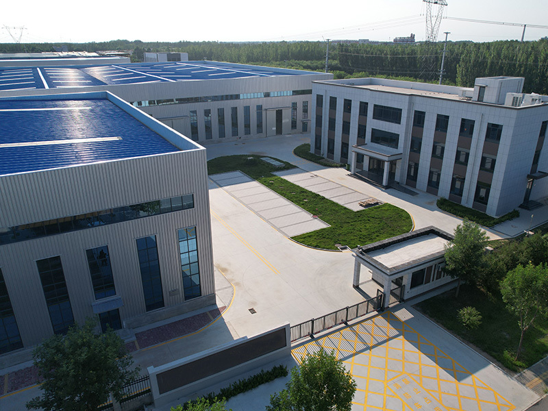
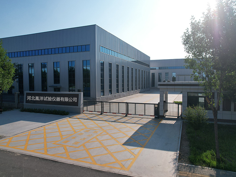
Hebei Yinfeng Experimental Instrument Co., Ltd. is a high-tech enterprise dedicated to the research and development, production, and sales of experimental instruments. The company is headquartered in Hebei Province, relying on the strong industrial foundation and technological innovation resources in the Beijing Tianjin Hebei region. It is committed to providing high-precision and high reliability testing equipment and solutions for material testing, engineering quality control, scientific research experiments and other fields.


Customized Delivery Process
We provide customers with full-process services ranging from pre-sale consultation, customized solution design, equipment installation and commissioning to after-sale technical support.
Online Communication
Provide Custom Drawings
Merchant Quotation
Sign A Contract
Processing And Production
Packaging And Distribution
Confirm Receipt Of Goods
Successful Transaction
Geotextile Permeability Tester
If you need customized products, Contact US !
Share to


Category
Tag list
Request a Quote
We will contact you within one working day. Please pay attention to your email.
Related Products
Content update in progress
Message
We will contact you within one business day. Please note your email address.
Fast navigation
Contact Us
Whatsapp/Tel: +86-15931715356,+86 16631790555
E-mail: qcj@cnhblabequipment.com
Add: Chengnan Industrial Zone, Xian County, Cangzhou City, Hebei Province

Online Message