


- Product Describe
-
Overview
The CH-DT401 dynamic resistance strain gauge is a dynamic acquisition instrument for various resistance strain gauges and strain sensors, including full bridge, half bridge, and quarter bridge configurations. It is also a data acquisition system for 0-4.8V voltage signals. The entire system uses a LAN interface for connection, allowing multiple instruments to be connected in series on-site. Each channel of the system can independently set the input for 1/4 bridge, 1/2 bridge, full bridge sensors, or voltage sensors, facilitating the mixed use of various sensors on-site. The system can also interface with our factory's GPRS-A wireless data acquisition system for remote on-site data monitoring.
The system has the following features:
1. Uses a 24-bit high-resolution AD conversion chip, ensuring stable and reliable data;
2. Each channel uses an independent chip for data acquisition, enhancing reliability and stability;
3. Each channel can independently set the bridge voltage;
4. Each channel can independently set the type of signal to be acquired;
5. Multiple sampling frequencies are available;
6. The system is equipped with a LAN interface for connection with general-purpose computers for data acquisition;
7. The system has a LAN interface that supports series connection of multiple devices and can connect to our factory's GPRS transmission equipment for wireless remote monitoring;
8. Industrial-grade component selection, suitable for use in environments from -20°C to 50°C;
Main Technical Parameters
1. Computer interface: LAN;
2. Number of measurement points per acquisition box: 4, 8, 16, 32, 60;
3. Maximum sampling frequency: dynamic 1000Hz;
4. A/D resolution: 24-bit;
5. Display method: computer display;
6. Control method: computer;
7. Expansion method: concentrator;
8. Maximum resolution: 1 με;
9. Measurement strain range: ±19999 με;
10. System uncertainty: no greater than 0.5% ± 3 με;
11. Drift (program-controlled state): ±3 με/4 hours (zero drift); ±1 με/°C (temperature drift);
12. Bridge excitation voltage: DC 2V, DC 5V; (For frequencies above 100Hz, please use 5V power supply; sensitivity is the same as 2V);
13. Power supply: AC 220V;
14. Power consumption: approximately 1.5W;
15. Operating environment: suitable for GB6587.1-86- Group II conditions;
16. Dimensions: 190mm (length) × 122mm (width) × 45mm (height);
17. Instrument weight: approximately 1kg;
Test Analysis System Panel Introduction
For the test analysis system panel, please refer to Figure 1 showing the CH-DT401 dynamic resistance strain gauge panel.
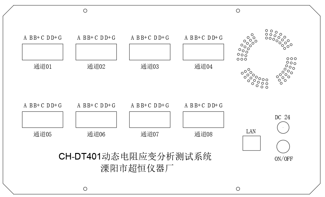
Front panel of CH-DT401 dynamic resistance strain gauge
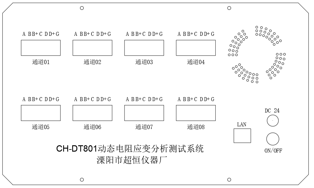
Front panel of CH-DT801 dynamic resistance strain gauge
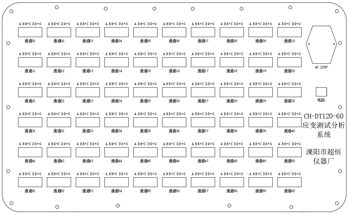
Figure 1: Front panel of CH-DT120 dynamic resistance strain gauge
Description of components in Figure 1:
1. Channels 01 to 60:
Used to connect sensors CH1 to CH60;
2. 24V+ and 24V0:
Provide 24V power externally;
3. LAN interface:
Used to connect to a computer;
- AC 220V:
Used for external power connection;
Used to turn the instrument on and off; position 1 is ON, position 0 is OFF.
Function Operation
4.1 Connecting Sensors
Connection of strain sensors is shown in Figure 2.
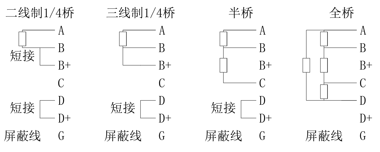
Figure 2: Wiring diagram of strain sensors
a. Full bridge sensor wiring: The full bridge sensor has 4 wires connected to terminals A, B, C, and D respectively. If there is a shield wire, connect it to G.
b. Half bridge sensor wiring: The half bridge sensor has 3 wires connected to terminals A, B, and C respectively. Short terminal D to the terminal below it. If there is a shield wire, connect it to G.
c. Quarter bridge sensor wiring: The quarter bridge sensor has 2 wires connected to terminals A and B respectively. Short terminal B to the terminal below it, and short terminal D to the terminal below it.
Connection of voltage sensors is shown in Figure 3.
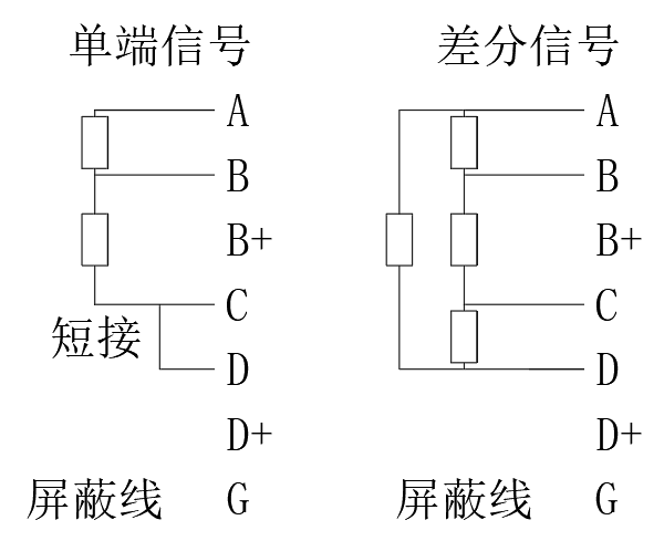
Figure 2: Wiring diagram of strain sensors
a. Differential sensor wiring: The differential sensor has 4 wires connected to terminals A, B, C, and D respectively. If there is a shield wire, connect it to G.
b. Single-ended sensor wiring: The single-ended sensor has 3 wires connected to terminals A, B, and C respectively. Short terminal D to C. If there is a shield wire, connect it to G.
4.2 Computer Software Installation:
This test system supports connection to a computer for sampling. To connect to a computer, install the computer program and device driver.
The device comes with a system USB drive. Open the system USB drive, extract "CH-DT401_Setup_0623", then run the "setup.exe" program and follow the computer prompts (Figure 4) to install the acquisition system.
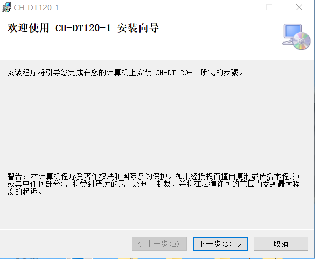
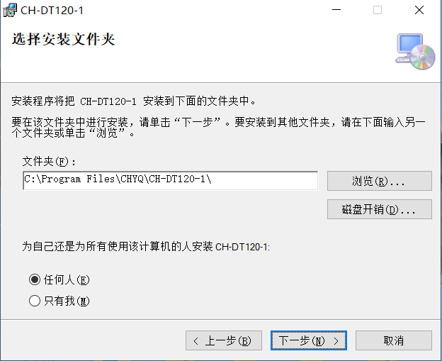
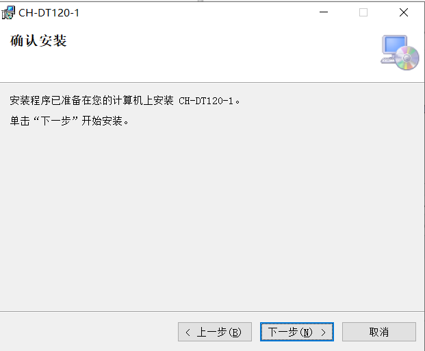
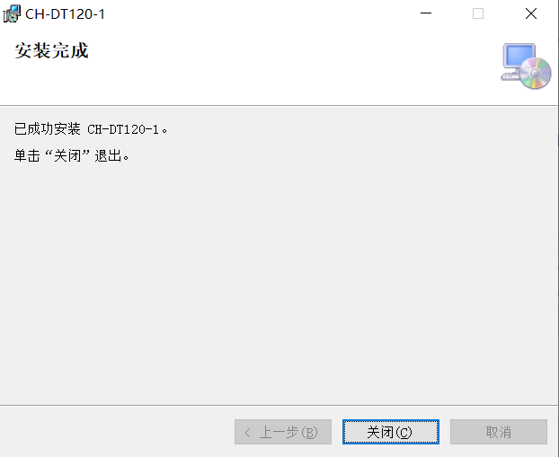
Figure 4 Installation Process
4.3 Computer Network Port Configuration:
When connecting the acquisition instrument to the computer, you must set a static IP address on the computer that is in the same subnet as the CH-DT401 IP; see Figure 5 below.
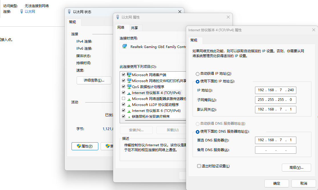
Figure 5 Computer Port Configuration
4.4 Complete Computer Data Acquisition Process:
(1) Connect the instrument to the computer
Connect the strain gauge and the computer via a LAN cable;
As introduced in 4.4, open the data acquisition program on the computer;
Turn on the strain gauge power;
Run the desktop shortcut "CH-DT401 Dynamic Signal Test Analysis System" program, the computer will display the measurement data window as shown in Figure 6.
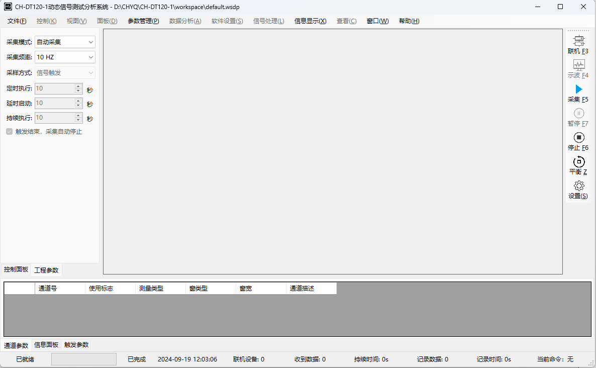
Figure 6 Computer Test Window
(2) Create a New Project
Click the "File" menu, then select "New Project" from the dropdown menu. See Figure 7.
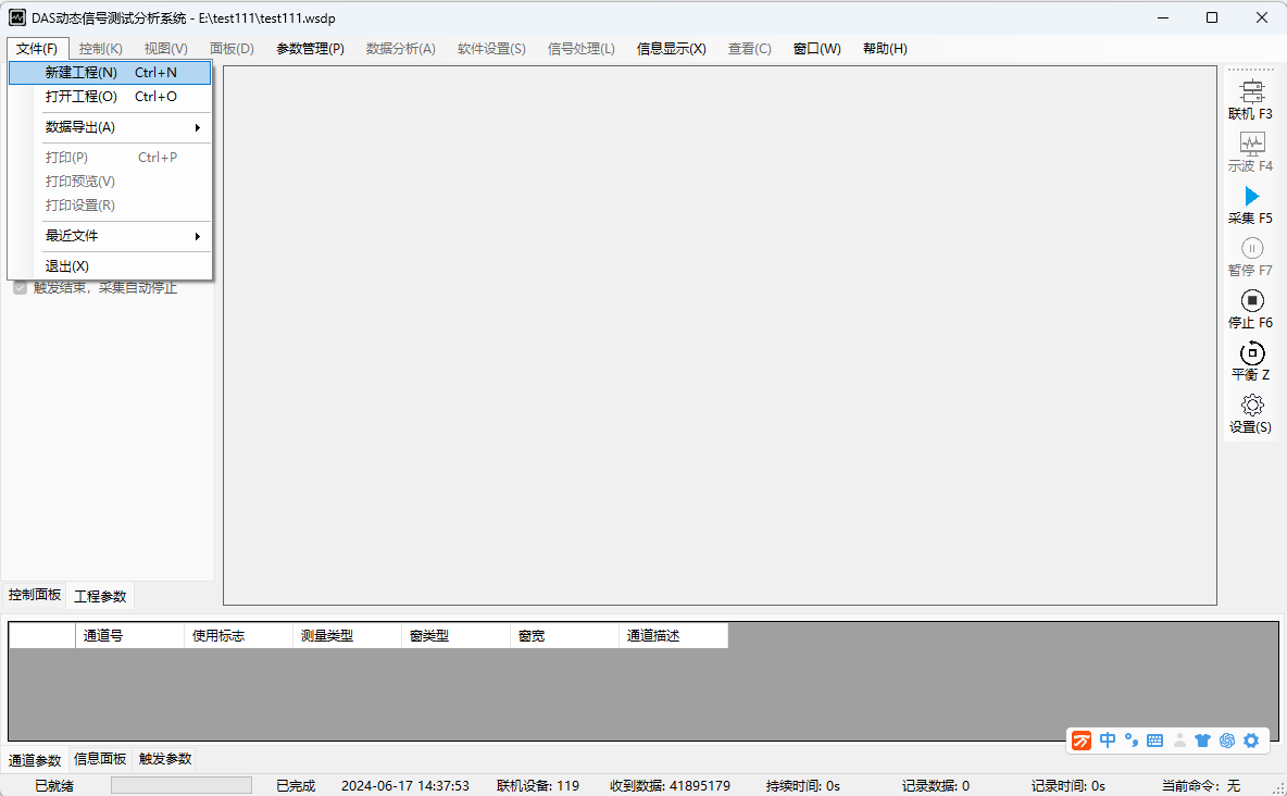
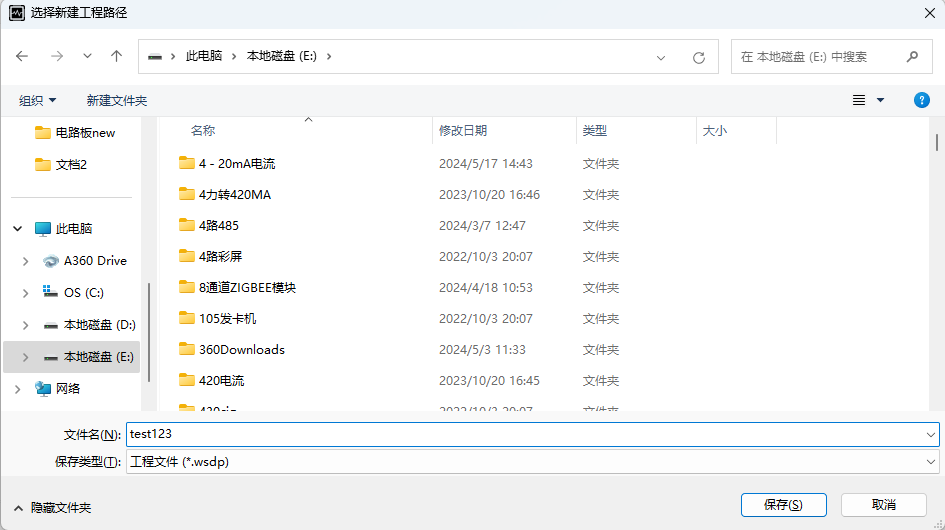
Figure 7 New Project
(3) Connect Device
After creating the project, click the "Connect" button on the right, the channel search window shown in Figure 8 will appear, displaying the number of currently connected channels.
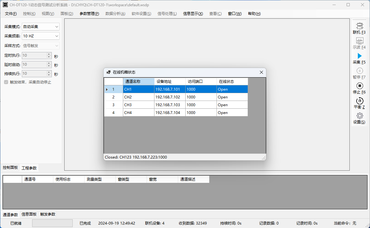
Figure 8 Search Measurement Channels
(4) Parameter Settings
Setting Method 1:
① Click the "Parameter Management" menu at the top of the computer, the window shown in Figure 9 will appear. Users can import and export parameters. Exported parameters are in an EXCEL spreadsheet, where users can modify data accordingly. See Figure 10.
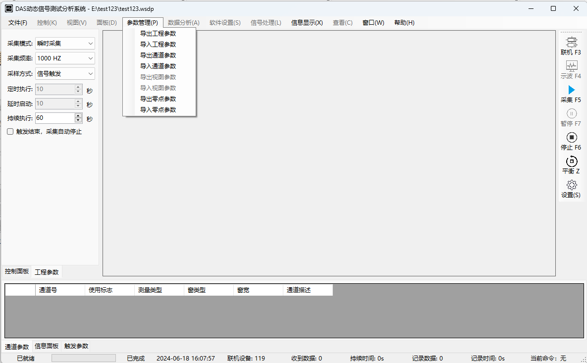
Figure 9 Parameter Import/Export Window
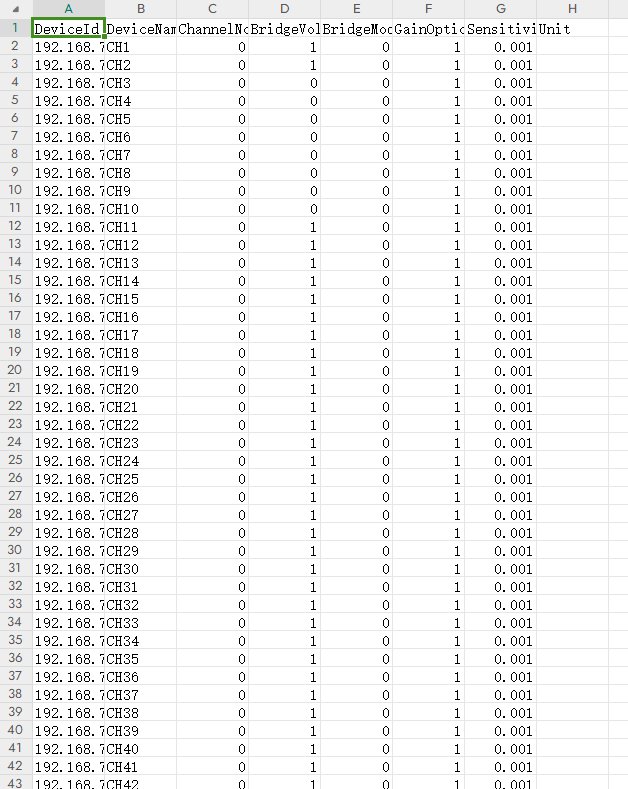
Figure 10 Parameter EXCEL Spreadsheet
Table Header Explanation:
DeviceId: Device network number (fixed value);
DeviceName: Channel number (fixed value);
ChannelNo: Channel number (editable);
BridgeVoltage: Bridge voltage (input value: 0=2V, 1=5V);
BridgeMode: Bridge mode (input value: 0=Sensor, 1=1/4 bridge, 2=1/2 bridge, 3=Full bridge);
GainOption: Amplification factor (input value: 0=Strain, 1=Voltage)
② Click the "Set" button on the right, the window shown in Figure 11 will appear. In the window, click "Upload Device Parameters", a prompt window shown in Figure 12 will appear. Click "Yes (Y)" to upload parameters to the device.
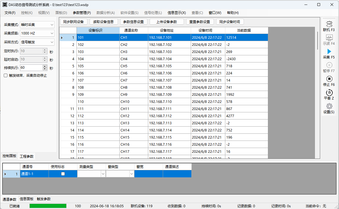
Figure 11 Channel Setting Window
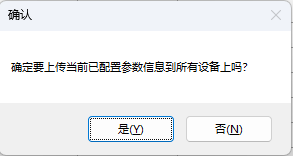
Figure 12 Upload Parameters Window
Setting Method 2:
For individual test parameters, in the window shown in Figure 11, select the channel to be modified, then select the "Information Panel" at the bottom left, the window shown in Figure 13 will appear.
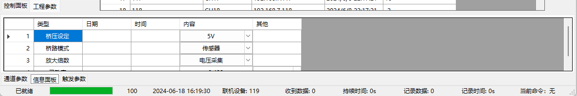
Figure 13 Single Parameter Setting
1. Bridge voltage setting, can be set to 2V or 5V operating conditions. (For frequencies above 100Hz, please use 5V power supply; sensitivity is the same as 2V) 。
2. Bridge mode, can set the type of connected sensor.
3. Amplification factor, can choose voltage signal or strain signal.
4. Sensitivity, for strain gauges it is 2, for strain sensors it is με/unit;
For voltage signals it is 5*mV/unit;
(5) Device Balance
Click the "Balance" button on the right to perform sensor balancing (zeroing). After clicking, the prompt window shown in Figure 13 will appear. Click "Yes" to balance. The device status at the bottom left will show "Balancing in progress". After completion, it will display "Balance completed."
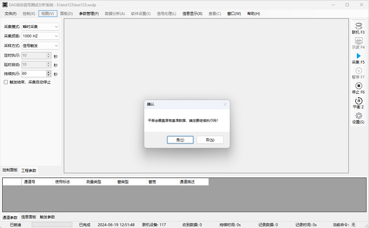
Figure 13 Balance Window
(6) Acquisition Mode Selection
As shown in Figure 14, the "Acquisition Mode" on the left side of the window can be selected. This instrument supports "Automatic Acquisition" and "Instantaneous Acquisition (Channel 1 triggered acquisition)".
The "Sampling Frequency" on the left side can be selected.
For "Instantaneous Acquisition", the acquisition time after triggering can be manually entered. For a single "Instantaneous Acquisition", please check "Stop acquisition automatically after trigger ends" below. For multiple "Instantaneous Acquisitions", do not check it.
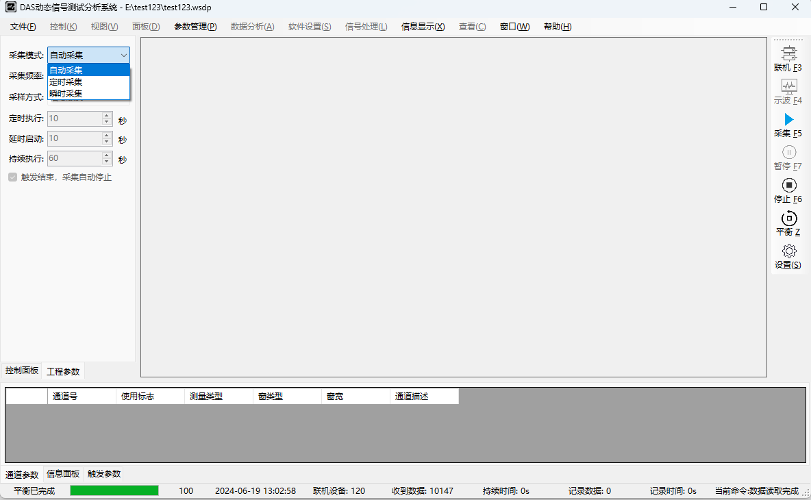
Figure 14 Acquisition Mode Selection
-9-
(7) Start Acquisition
Click the "Acquire" button on the right to start data acquisition.
(8) Display Curve
Click the "Oscilloscope" button on the right, the window shown in Figure 15 will appear. Users can check the curves to display (up to 8), then click "Start Oscilloscope". The software will display the curve window as shown in Figure 16.
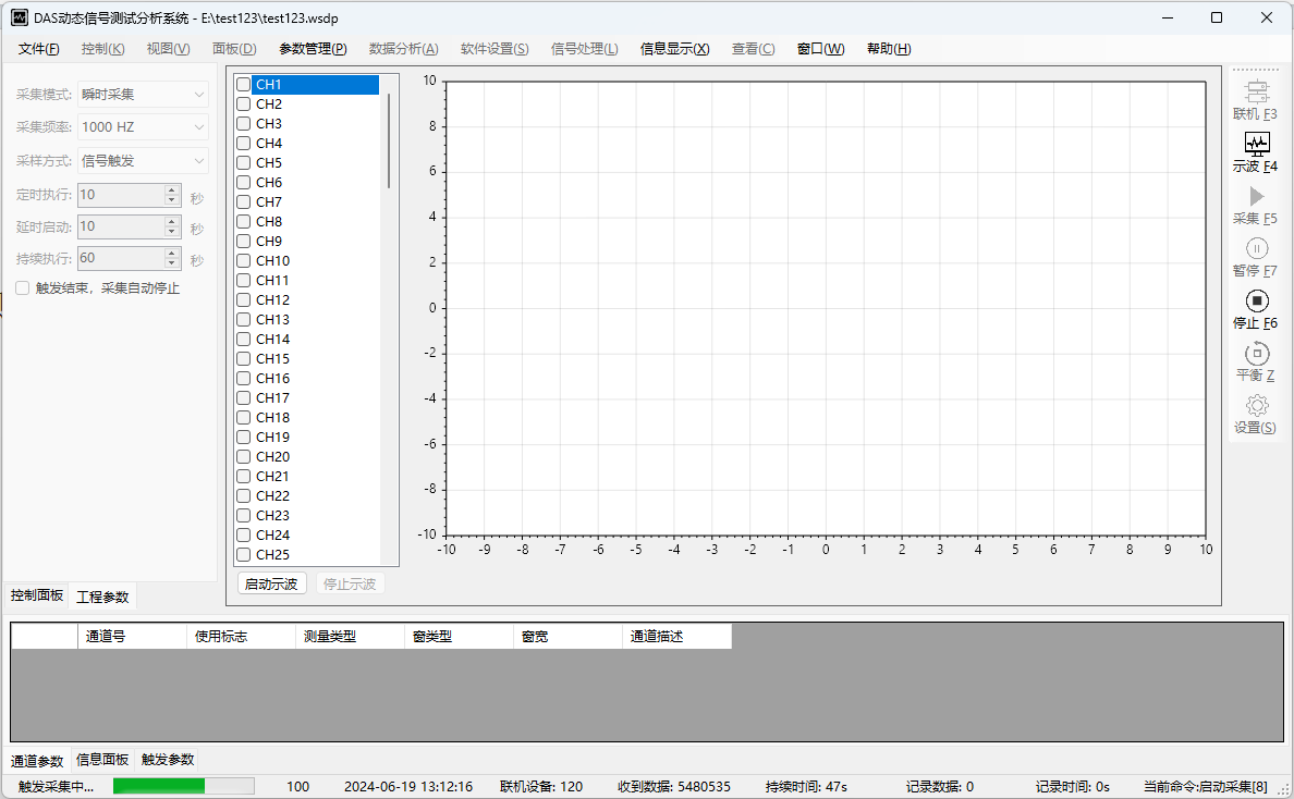
Figure 15 Select Graph Window
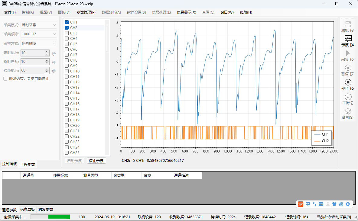
Figure 16 Curve Display Window
-10-
(9) Stop Acquisition
Click the "Stop" button on the right to synchronize the device. After clicking, the device status at the bottom left will show "Stopping". After stopping, it will display "Ready."
(10) Export Data
Click the "File" menu, then select "Export Data" from the dropdown menu. See Figure 17. A prompt window shown in Figure 18 will pop up. Click "Export" and wait for the file to be exported.
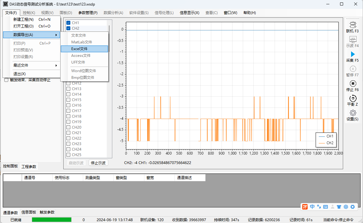
Figure 17 File Export Window
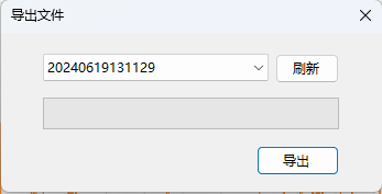
Figure 18 File Export Prompt
Quality Assurance and Technical Support
Our factory provides a one-year warranty for the dynamic resistance strain gauges produced. During the warranty period, the product is covered by the three guarantees, except for damages caused by human factors or natural environmental disasters.
Company Profile
Hebei Yinfeng Experimental Instrument Co., Ltd. is a high-tech enterprise dedicated to the research and development, production, and sales of experimental instruments. The company is headquartered in Hebei Province, relying on the strong industrial foundation and technological innovation resources in the Beijing Tianjin Hebei region. It is committed to providing high-precision and high reliability testing equipment and solutions for material testing, engineering quality control, scientific research experiments and other fields.


Customized Delivery Process
We provide customers with full-process services ranging from pre-sale consultation, customized solution design, equipment installation and commissioning to after-sale technical support.
Online Communication
Provide Custom Drawings
Merchant Quotation
Sign A Contract
Processing And Production
Packaging And Distribution
Confirm Receipt Of Goods
Successful Transaction
Previous:
Dynamic and Static Strain Gauge
If you need customized products, Contact US !
Share to


Category
Tag list
Request a Quote
We will contact you within one working day. Please pay attention to your email.
Related Products
Content update in progress
Message
We will contact you within one business day. Please note your email address.
Fast navigation
Contact Us
Whatsapp/Tel: +86-15931715356,+86 16631790555
E-mail: qcj@cnhblabequipment.com
Add: Chengnan Industrial Zone, Xian County, Cangzhou City, Hebei Province

Online Message