


- Product Describe
-
Instruction Manual for the New Standard Heavy-Duty Dynamic Penetrometer
1. General Provisions
(1) The cone penetration test is suitable for gravelly soils, sandy soils, and cohesive soils. It can be used to evaluate the density of foundation soils and to determine their deformation modulus and bearing capacity.
(2) The cone penetration test can be classified into light-duty cone penetration test, heavy-duty cone penetration test, and extra-heavy-duty cone penetration test.
Three types of dynamic penetration tests.
(3) On the same site, the number of cone penetration test boreholes should not be less than 3, and the number of test points in each soil layer should not be less than 6.
2 Test Equipment
(1) The cone penetration test equipment shall consist of a drop hammer, a probe tip, a hammer pad, a guide rod, and a penetration rod.
The drop hammer, probe tip, hammer pad, guide rod, and penetration rod shall all be made of corrosion- and wear-resistant steel, and their specifications shall comply with the provisions in Table 2.2.
Table 2.2 Main Technical Parameters of the Cone Dynamic Penetration Test Equipment
Type Lightweight Heavy Super-heavyweight Drop hammer Mass (kg) 10 ± 0.1 63.5 ± 0.5 120 ± 1 Drop distance (mm) 500 ± 20 760 ± 20 1000 ± 20 Probe Conical end diameter (mm) 40 74 74 Cross-sectional area (cm²) 12.6 43 43 Cone angle (°) 60 60 60 Probe rod Diameter (mm) 25 ± 0.5 42 ± 0.5 50~60 Indicator Penetration reading at 30 cm: N. Penetration 10 cm reading Nas Penetration reading at 10 cm: N2a (3) The external dimensions of the light-duty cone penetration test probe shall comply with the specifications shown in Figure 2.3-1. The external dimensions of the heavy-duty and extra-heavy-duty cone penetration test probes shall comply with the specifications shown in Figure 2.3-2. After surface hardening, the hardness of the probe shall be greater than HRC40. The maximum allowable wear dimension of the probe diameter shall not exceed 2 mm, and the maximum allowable wear dimension of the cone tip height shall not exceed 5 mm.
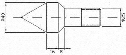
Figure 2.3-1: External Dimensions of the Lightweight Cone Dynamic Penetration Probe (Dimension Unit: mm)
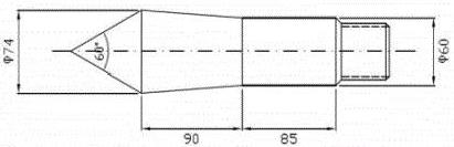
Figure 2.3-2: External Dimensions of Heavy and Ultra-Heavy Cone Dynamic Penetration Probes (Dimension Unit: mm)
(4) The tensile strength of the probing rod shall be greater than 600 MPa. The probing rod shall be straight, and all threaded connections between components shall be intact and securely fastened.
(5) The diameter of the hammer pad should be less than half the diameter of the falling hammer and greater than 100 mm. The length of the guide rod should meet the requirements for the drop height. Hammer
The total mass of the pad and guide rod should not exceed 30 kg. The central axes of the hammer pad, guide rod, and probing rod must be aligned in a straight line.
(6) The drop hammer shall be cylindrical, with a height-to-diameter ratio of 1 to 2. The diameter of the circular hole at the center of the drop hammer should be 3 to 4 mm larger than the outer diameter of the guide rod.
(7) The cone penetration test equipment shall be equipped with an automatic release mechanism to ensure that the hammer falls freely. The hammer should be calibrated regularly, and the drop height of the hammer should be checked before each test.
3. Test Method
(1) Before conducting the cone penetration test, the equipment should be inspected to ensure that all components meet the required specifications. Components that show wear or deformation exceeding the specified limits must be replaced or repaired.
(2) The machinery and equipment shall be installed securely, and the support frame must not shift during operation. All threaded connections must be tightly fastened.
(3) During the test, first drill to the predetermined test depth using the drilling tool, then gently lower the dynamic penetrometer tip to the bottom of the borehole. Impacting is strictly prohibited.
Strike or press into the soil layer.
(4) During cone penetration testing, the verticality of the probe rod and guide rod after they are connected must be maintained. The hammer should always fall vertically along the guide rod to prevent eccentric hammering, tilting of the probe rod, or lateral swaying. The hammering frequency should be controlled within the range of 15 to 30 blows per minute.
(5) The light cone penetration test shall comply with the following provisions:
1. During lightweight cone penetration testing, the test soil layer should be continuously penetrated downward.
2. For continuous penetration tests, the drop height of the center-punch hammer should be 50 cm, and the hammer should be allowed to fall freely. The height of the hammer pad above the borehole opening is...
No more than 1.5 m
3 The number of hammer blows required to drive the sampler 30 cm into the ground is used as the test criterion and is denoted by N. In the case of dense soil layers, when the sampler has been driven 30 cm...
The test may be stopped when the number of hammer blows exceeds 90, or when the number of hammer blows required to penetrate 15 cm exceeds 45.
(6) Heavy and extra-heavy cone penetration tests shall comply with the following provisions:
1. The drop height for the heavy-duty cone penetration test should be 76 cm; the drop height for the extra-heavy-duty cone penetration test should...
For the 100-cm drop hammer, it should fall freely along the guide rod; the height of the hammer pad above the hole opening should not exceed 1.5 m.
2. The hammer blows shall be delivered continuously. Both the heavy-duty cone penetration test and the extra-heavy-duty cone penetration test shall be conducted at intervals of 10 cm per penetration.
The number of hammer blows is used as the test indicator and is represented by Ness and N₂o, respectively.
3. The heavy-duty and extra-heavy-duty cone penetration tests can be interchanged based on changes in stratum strength. Heavy-duty cone penetration test
When the measured number of blows in the test exceeds 50 blows/10 cm, it is advisable to switch to the extra-heavy-duty cone penetration test; heavy-duty cone penetration.
When the measured number of blows in the penetration test is less than 5 blows/10 cm, the extra-heavy-duty cone dynamic penetration test should not be used.
4. The test can be conducted in segments within the borehole, and each test segment should be carried out continuously without any interruptions in between.
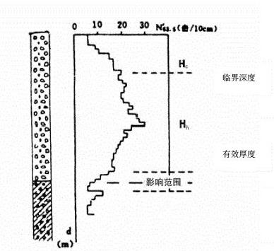
Figure 6.4.7: Curve showing the relationship between the corrected number of hammer blows and penetration depth for the cone dynamic penetration test.
4. When the effective thickness of the soil layer is less than 0.3 m, the average number of blows from the heavy cone dynamic penetration test can be determined according to the following principles:
(1) When both the upper and lower layers are soil layers with relatively low blow counts, N₆₃₅ can be taken as the larger of the two blow counts obtained from the standard penetration test in that layer, Ne₃ₛmax.
(2) When both the upper and lower layers are soils with relatively high blow counts, N₆s should be taken as the smaller value between this layer’s standard penetration test blow count and Neas mn.
(3) The characteristic value of the bearing capacity of foundations in cohesive soils, fo, can be determined based on the Nro values of the soil layers at the site when the penetration depth is less than 4 m.
Table 4.3.3: Determine.
Table 4.3.3 Characteristic value of bearing capacity of cohesive soil foundation, fan (kPa)
N₁o (hit 130cm) 15 20 25 30 FAO 100 140 180 220 Note: The values in the table can be linearly interpolated.
(4) The characteristic values of bearing capacity, fo, for medium sand, coarse sand, gravelly sand, and gravelly soil foundations formed by alluvial and fluvial processes: When the penetration depth is less than 20 m, the values can be determined according to Table 4.5-1 and Table 4.5-2 based on the Ness classification of the site’s soil layers [image].
(5) The characteristic values of bearing capacity Ja for medium sand, coarse sand, gravelly sand, and rubble foundations formed by alluvial and fluvial deposits can be determined according to Table 4.5-1 and Table 4.5-2 based on the Na values of the site’s soil layers, provided that the penetration depth is less than 20 m.
Table 4.5-1: Characteristic values of bearing capacity (kPa) for medium sand, fine sand, and gravelly sand.
Nn. (Strike/10m) 3 4 5. 6 7 8 9 10 f 120 150 180 2m 260 300 340 380 Note: This table generally applies to alluvial and colluvial sandy soils; however, the coefficient of uniformity for medium- and coarse-grained sands should not exceed 6, and for well-sorted sands, it should not exceed 20.
Table 4.5-2: Characteristic Value of Bearing Capacity of Gravel Soil Foundation / (tPs)
Na: (Hit/10m) 3 5 6 7 8 9 10 12 14 5 140 170 200 240 20 320 360 400 480 540 a: (impact/10 cm) 16 18 20 22 24 26 28 30 35 40 f 600 660 720 780 830 870 900 980 970 1.000 (6) The deformation modulus E of pebbles and rounded gravel formed by alluvial and colluvial processes can be determined according to Table 4.6-1 based on the Na value of the site’s soil layers, provided that the penetration depth is less than 12 m.
Table 4.6-1: Deformation Modulus E Values (MPa) for Pebbles and Gravel Clods
(Hit/10cm) 3 4 5 6 8 10 12 14 16 5 9 1 14 17 22 27 31 36 40 (Hit/10cm) 18 20 222 24 25 28 30 35 40 E 44 47 50 56 58 60 64 66 4.7 Based on the number of blows N from the heavy and extra-heavy cone penetration tests, as well as Nm, the compactness of gravelly soils can be determined according to Table 4.7-1 and Table 4.7-2. The values of Na and Nm in these tables shall be corrected in accordance with the provisions of this code.
Table 4.7-1: Classification of Gravelly Soil Compactness Based on Heavy Cone Penetration Test
Na, (hit/10 cm) Na; ≤5 5 < Na ≤ 10 10 < Nas ≤ 20 Nas>20 Density Loose Slightly dense Medium density Dense Note: This table applies to gravelly soils with an average particle size equal to or less than 50 mm and a maximum particle size less than 100 mm.
Table 4.7-2: Classification of Gravelly Soil Compactness Based on Ultra-Heavy Cone Penetration Test with Dynamic Loading
Nm (hits/10 cm) N<3 3 < N ≤ 6 6 < N < 11 N>11 Density Loose Slightly dense Medium density Dense Note: This table applies to gravelly soils with an average particle size greater than 50 mm or a maximum particle size greater than 100 mm.
Company Profile
Hebei Yinfeng Experimental Instrument Co., Ltd. is a high-tech enterprise dedicated to the research and development, production, and sales of experimental instruments. The company is headquartered in Hebei Province, relying on the strong industrial foundation and technological innovation resources in the Beijing Tianjin Hebei region. It is committed to providing high-precision and high reliability testing equipment and solutions for material testing, engineering quality control, scientific research experiments and other fields.


Customized Delivery Process
We provide customers with full-process services ranging from pre-sale consultation, customized solution design, equipment installation and commissioning to after-sale technical support.
Online Communication
Provide Custom Drawings
Merchant Quotation
Sign A Contract
Processing And Production
Packaging And Distribution
Confirm Receipt Of Goods
Successful Transaction
Previous:
Penetration tester
If you need customized products, Contact US !
Share to


Category
Tag list
Request a Quote
We will contact you within one working day. Please pay attention to your email.
Related Products
Content update in progress
Message
We will contact you within one business day. Please note your email address.
Fast navigation
Contact Us
Whatsapp/Tel: +86-15931715356,+86 16631790555
E-mail: qcj@cnhblabequipment.com
Add: Chengnan Industrial Zone, Xian County, Cangzhou City, Hebei Province

Online Message