



- Product Describe
-
Overview
Scope of Application for the HT-950 Drop-Ball Resilience Modulus Tester This instrument is manufactured in accordance with the industry standards of the People’s Republic of China and complies with the requirements of the JTJ059-59 Code for On-Site Testing of Highway Subgrades and Pavements. It is now in mass production and available for supply. The instrument is suitable for the rapid on-site determination of the in-situ CBR value of fine-grained soils, offering high test accuracy, reliable methodology, and quick, simple operation, thereby meeting the requirements of subgrade construction sites.
Instrument Structure
The falling-ball rebound modulus tester, whose structure and configuration are shown in the figure, consists of a base, a falling-ball moving frame, guide rods and a falling ball, a guide-rod bayonet release switch, a graduated pointer, a depth scale, and a leveling bubble. It is supplied with 100 mm and 150 mm base adapter plates and is suitable for laboratory compaction testing of soil samples.
Main Technical Parameters
1. Total mass of the falling ball and guide rod: 4.5 kg ± 0.01 kg
2. Drop height: 600 ± 0.5 mm
3. Drop ball radius: 47 ± 0.1 mm
4. Drop-ball depth indication accuracy: 0.5 mm
How to Use
1. The instrument test must be conducted systematically: the subgrade surface shall be scraped smooth, and measurements shall be taken immediately after compaction of the subgrade testing layer. The procedure is as follows: place the base of the falling-weight deflectometer on the leveled subgrade surface at the measurement location; adjust the upper scale mark on the guide rod so that it aligns precisely with the zero mark on the reference scale; then raise the guide rod to a height of 600 mm, which corresponds to the standard drop height, and lock the guide rod in place using the locking mechanism. At this point, the lower scale mark on the falling-weight deflectometer should align exactly with the zero mark on the reference scale. When the locking release switch is pressed, the guide rod and the falling weight will free-fall onto the subgrade, and the deflection gauge window can be used to read the diameter (in cm) and depth of the fall-weight-induced depression, denoted by D. Next, lift the guide rod above the ground, reposition the base, and use a caliper-type steel ruler to measure the precise value of the fall-weight-induced depression diameter D. Record the results accordingly.
2. When testing compacted soil samples in the laboratory using test cylinders, either 100 mm or 150 mm cylinders may be used. The instrument is equipped with a dual-purpose plate that can be used on both sides: the 100 mm side for 100 mm cylinders and the 150 mm side for 150 mm cylinders; all other operating procedures remain the same as above.
3. When the ball imprint on the coarse-sand subgrade is unclear, the subgrade surface may be leveled and then sequentially covered with recording paper, carbon paper, and plastic film. Upon impact of the ball on the recording paper, the diameter D of the imprint can be measured directly on the paper and verified against the scale reading.
4. At each measurement point, determine the D value in parallel on both sides and then calculate the average. 8.2.4 Data Compilation.
The in-situ CBR value shall be calculated from the measured diameter D of the ball-drop imprint using Equation (8.2.4-1).
On-site CBR = C.a (8.2.4-2)
In the formula: C is the effective coefficient, determined through established correlation relationships; when such conditions are not available, a value of 0.35 may be adopted for cohesive soils and 0.45 for sandy soils.
Instrument constant α of the falling-ball viscometer
D a D a D a D a 2.5 1332.33 3.7 209.85 4.9 54.28 6.1 18.25 2.6 1108.39 3.8 184.79 5.0 49.16 6.2 16.79 2.7 928.82 3.9 163.24 5.1 44.62 6.3 15.47 2.8 782.97 4.0 144.63 5.2 40.50 6.4 14.26 2.9 664.01 4.1 128.52 5.3 36.95 6.5 13.16 3.0 565.95 4.2 114.63 5.4 33.65 6.6 12.15 3.1 485.29 4.3 102.23 5.5 30.72 6.7 11.23 3.2 417.56 4.4 91.49 5.6 28.09 6.8 10.39 3.3 361.16 4.5 82.08 5.7 25.69 6.9 9.61 3.4 313.58 4.6 73.82 5.8 23.56 7.0 8.90 3.5 273.33 4.7 66.49 5.9 21.62 7.1 8.24 3.6 239.07 4.8 60.01 6.0 19.85 7.2 7.64 In the formula: D represents the diameter of the ball-drop indentation (cm);
W: The guide rod and the falling ball weigh 4.5 kg.
The drop height of the spherical object is 60 cm.
The radius of the sphere is 4.7 cm.
Company Profile
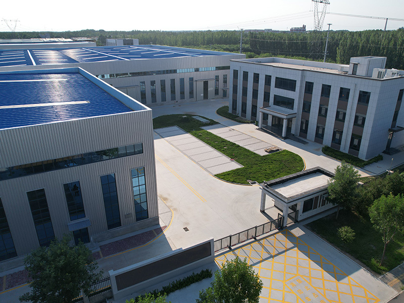
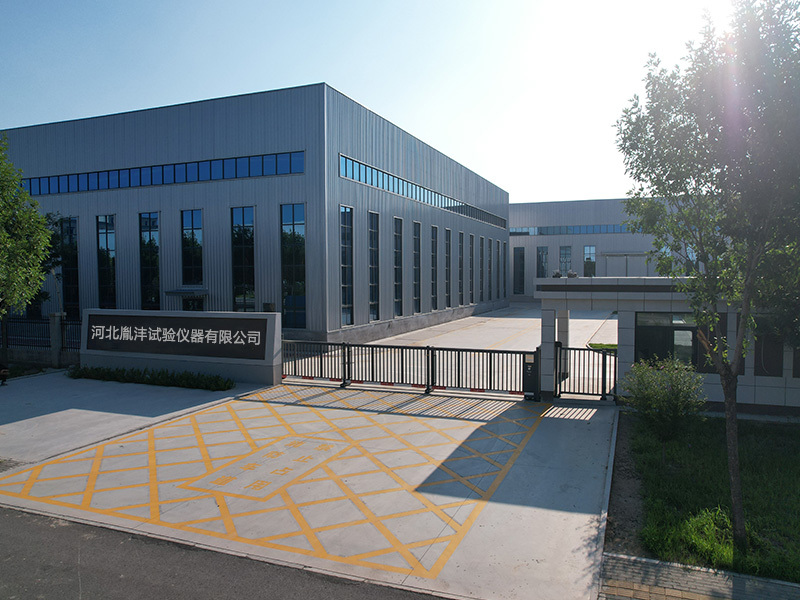
Hebei Yinfeng Experimental Instrument Co., Ltd. is a high-tech enterprise dedicated to the research and development, production, and sales of experimental instruments. The company is headquartered in Hebei Province, relying on the strong industrial foundation and technological innovation resources in the Beijing Tianjin Hebei region. It is committed to providing high-precision and high reliability testing equipment and solutions for material testing, engineering quality control, scientific research experiments and other fields.


Customized Delivery Process
We provide customers with full-process services ranging from pre-sale consultation, customized solution design, equipment installation and commissioning to after-sale technical support.
Online Communication
Provide Custom Drawings
Merchant Quotation
Sign A Contract
Processing And Production
Packaging And Distribution
Confirm Receipt Of Goods
Successful Transaction
Fall-Weight Rebound Modulus Tester
If you need customized products, Contact US !
Share to


Category
Tag list
Request a Quote
We will contact you within one working day. Please pay attention to your email.
Related Products
Content update in progress
Message
We will contact you within one business day. Please note your email address.
Fast navigation
Contact Us
Whatsapp/Tel: +86-15931715356,+86 16631790555
E-mail: qcj@cnhblabequipment.com
Add: Chengnan Industrial Zone, Xian County, Cangzhou City, Hebei Province

Online Message